
|
Journal of Cancer Research and Therapeutics
Medknow Publications on behalf of the Association of Radiation Oncologists of India (AROI)
ISSN: 0973-1482 EISSN: 1998-4138
Vol. 4, Num. 2, 2008, pp. 70-76
|
Journal of Cancer Research and Therapeutics, Vol. 4, No. 2, April-June, 2008, pp. 70-76
Original Article
Comparison of geometric uncertainties using electronic portal imaging device in focal three-dimensional conformal radiation therapy using different head supports
Budrukkar Ashwini, Dutta Debnarayan, Sharma Dayanand, Yadav Premnath, Dantas Smitha, Jalali Rakesh
Department of Radiation Oncology, Tata Memorial Hospital, Parel, Mumbai
Correspondence Address:Department of Radiation Oncology, Tata Memorial Hospital, Parel, Mumbai - 400 012,
ashwininb@yahoo.com
Code Number: cr08020
Abstract
Aims and Objectives: To study the geometric uncertainties in the treatment and evaluate the adequacy of the margins employed for planning target volume (PTV) generation in the treatment of focal conformal radiotherapy (CRT) for patients with brain tumors treated with different head support systems.
Materials and Methods: The study population included 11 patients with brain tumors who were to be treated with CRT. Contrast-enhanced planning CT scan (5-mm spacing and reconstructed to 2 mm) of brain were performed. Five patients were immobilized using neck support only (NR-only) and six patients had neck support with flexion (NRF), the form of immobilization being decided by the likely beam arrangements to be employed for that particular patient. The data was transferred to the planning system (CadPlan) where three-dimensional conformal radiation therapy was planned. Digitally reconstructed radiographs (DRRs) were created for the orthogonal portals with the fixed field sizes of 10 × 10 taken at the isocenter. Treatment verification was done using an amorphous silicon detector portal imaging device for using orthogonal portals and the DRR was used as a reference image. An image matching software was used to match the anatomical landmarks in the DRR and the portal imaging and the displacement of the portals in x, y axis and rotation were noted in the anteroposterior (AP) and lateral images. Electronic portal imaging was repeated twice weekly and an average of 8-14 images per patient was recorded. The mean deviation in all the directions was calculated for the each patient. Comparison of setup errors between the two head support systems was done.
Results: A total 224 images were studied in anterior and lateral portals. The patient group with NR-only had 100 images, while the NRF group had 124 images. The mean total error in all patients, NR-only group, and NRF group was 0.33 mm, 0.24 mm, and 0.79 mm in the mediolateral (ML) direction; 1.16 mm, 0.14 mm, and 2.22 mm in the AP direction; and 0.67 mm, 0.31 mm, and 0.96 mm in the superoinferior (SI) direction, respectively. The systematic error (S) in all patients, NR-only group, and NRF group in the ML direction was 0.31 mm, 0.28 mm, and 0.78 mm; 1.29 mm, 0.1 mm, and 2.24 mm in the AP direction; and 0.75 mm, 0.52 mm, and 0.94 mm in the SI direction, respectively. Random error (s) in all patients, NR-only group, and NRF group in the ML direction was 1.25 mm, 1.04 mm, and 1.41 mm; 1.31 mm, 1.36 mm, and 1.28 mm in the AP direction; 1.38 mm, 1.37 mm, and 1.39 mm in the SI direction, respectively. In all patients, the PTV margin with Stroom's formula in the NR-only and NRF group was 1.29 mm and 2.55 mm in the ML, 1.15 mm and 5.38 mm in the AP, and 2.0 mm and 2.85 mm in the SI directions, respectively.
Conclusion: A PTV margin of 5 mm appears to be adequate; further reduction to 3 mm may be considered based on our results. Errors were significantly higher in the AP direction with NRF when compared to NR-only. Differential PTV margin may therefore be considered, with more margin in the AP and less in other directions, especially with the use of flexion devices.
Keywords: Brain tumor, electronic portal imaging device, head support
Conventional radiation therapy to the majority of brain tumors involves 2-3 static open beams with a simple coplanar field arrangement. The field dimensions are chosen to cover the tumor adequately as deemed appropriate on planning X-ray images (as on a simulator) with respect to the surface and bony anatomy. [1] Typically, a generous margin of 1-2 cm is given in order to overcome the possible errors in judging the coverage of the tumor, its microscopic extension, and the uncertainties in daily setup and treatment delivery. [2] This may lead to irradiation of significant volumes of normal brain and adjacent critical structures. With three-dimensional conformal radiation therapy (CRT) it is possible to achieve a high dose differential between the tumor and the surrounding normal tissues, which may allow for either an increase in the tumor dose to improve local control or for a potential decrease in radiation damage to the normal brain. Planning target volume (PTV) is created to take into account the setup uncertainties, which include inaccuracies in laser alignment, gantry and couch stability, plan implementation, and day-to-day patient movement. [3],[4],[5] Generally, the CTV to PTV margin in various studies in brain tumors ranges between 3 mm to 1 cm. [6],[7],[8],[9],[10],[11] However, it is important that each institution should develop its own margin growing protocols based on the available immobilization devices and portal imaging data. While implementing CRT it is imperative to have stringent quality assurance for the radiation therapy treatment planning and execution. Quality assurance for the treatment execution can be done by portal films, which are typically done once a week or by using electronic portal imaging. [12] We have earlier published our results with the use of conservative margins in patients with benign and low-grade tumors treated with 6-MV LA (Varian 2100CD). [8]
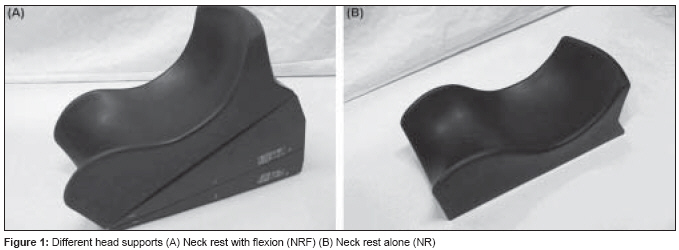
In brain tumors, different head rests [only neck support (NR) or neck support with flexion (NRF)] are used to provide appropriate flexion of the head and to exclude critical structures like the eye and lens from the treatment portal [Figure - 1]. In the flexed position (NRF), treatment delivery is possible without couch rotation and thus decreases couch movement-related uncertainties. Sparing of critical structures is possible with anterior and lateral fields. However, such positions may introduce more setup uncertainties. With the use of different immobilization devices, the PTV margins are generally not modified. Therefore, there is a need to ascertain the setup margins using different immobilization devices. With the availability of 6-MV LA with micro-multileaf collimators (Clinac 6EX), the present study was done to evaluate the geometric inaccuracies in the CRT for brain tumors using electronic portal imaging device (EPID), to evaluate the random and systematic errors, and the adequacy of clinical target volume (CTV) to planning target volume (PTV) margins. The role of different head supports was also evaluated and the setup uncertainties were measured.
Materials and Methods
Eleven patients with brain tumours who were considered for focal irradiation with 3DCRT and planned for treatment with Clinac 6EX were enrolled in this prospective study. Patients were immobilized using different head supports (NR-only or NRF) and a customized thermoplastic mould with three-point fixation: one at the vertex and two on either side of the head. Six suitable patients were treated with NRF and five patients with NR. Most of the patients had midline tumours.
Radiotherapy planning
Patients immobilized in their moulds underwent contrast-enhanced planning CT scans with 3-mm slice thickness at 2-5 mm separation. The CT data of each patient was networked to the dedicated treatment planning system (CadPlan, Varian). GTV was defined as the area of visible tumor, or areas deemed to contain tumor, and was manually contoured by the clinician on each CT slice. All pretreatment imaging was reviewed to help in defining this volume. Critical structures such as the optic chiasm, pituitary-hypothalamic axis, brain stem, and the normal brain were also contoured. CTV was drawn taking into account the possible microscopic extension of the tumor not seen on the planning images. This margin depends upon the type of tumor and the confidence in tumor volume definition and generally ranges between 5 mm to 2 cm. At our center, typically, a margin of 5 mm is grown around the CTV to give the final PTV.
Field arrangement and plan evaluation
Treatment planning was based on planning optimization utilizing beam energy, appropriate weighting, and wedges with different field arrangements. The plans were finalized using ICRU 62 recommendations, ensuring PTV coverage by 95% isodose line and maintaining uniform dose homogeneity. [5],[6] CRT plans typically involved 3-4 conformal field arrangements. With the help of beam′s eye view facility, conformation was achieved for all fields with standard multileaf collimators of 5-mm leaf width at the isocenter. Analysis of rival plans was done by visual assessment and with the help of dose-volume histograms (DVH) of the PTV and critical structures. The plan that delivered uniform dose distribution to the PTV, with adequate coverage and minimal possible doses to the normal brain and adjacent critical structures, was chosen as the final plan. Treatment parameters were then transferred through network to the treatment machine (Clinac 6Ex, Varian), where the treatment was delivered by 6-MV photons.
Digitally reconstructed radiographs (DRR)
DRRs were created for the fixed field size 10 x 10 cm for the gantry angles 0° and 90° and were transferred to the Portal Vision software. The match structures were drawn manually by the clinician on the anterior and lateral DRR. Typically, the match structure in the anterior DRR was the parietal bone and the orbital ridges, while in the lateral DRR it was the parietal and the occipital or frontal bone.
Electronic portal imaging (EPI)
Portal images were acquired using amorphous silicon detector aS500 (Varian Medical Systems) attached to Clinac 6EX. The portal images were acquired at the isocenter with a fixed field size of 10 x 10 cm and gantry angles of 0° and 90°. The images were acquired by using 4 MU per field. Imaging was done twice weekly for each patient and thus 10-12 sets of images were available for each patient.
Image matching
Matching of the DRR with EPI was done with the image matching software. The match structures along with the field formed the match template, which was matched with the portal image with automatic image matching software and then adjusted further manually to the visible bony anatomy of the portal image. The resulting difference in the planned and the delivered field was then given by the image matching software. In the anterior field mediolateral (ML), superoinferior (SI), and rotation in the coronal plane were detected, while in the lateral film anteroposterior (AP), SI, and rotation in the sagittal plane were detected. Portal imaging was done before treatment and the setup error was assessed. The offline correction protocol was made to correct the setup errors if the mismatch was more than 3 mm in any direction. No action was taken if the mismatch was within 3 mm in all directions. Treatment was delivered with corrected setup and portal imaging was done the next day to confirm the correction.
On the day of starting of treatment, portal imaging was not taken. This decision was taken considering the patient′s anxiety on the day of starting treatment and the increased apprehension if the treatment time is prolonged due to portal imaging. Thus, in our protocol, portal imaging was taken on day 2 and then twice weekly. Patient compliance was always taken into account while ensuring regular imaging.
Data analysis
For each direction, and for each individual patient, measurement of the displacement between the DRR and one single treatment session represents the total error in patient positioning for the treatment session under consideration. This displacement is a combination of both systematic and random errors. The systematic error for each individual patient is represented by the mean value of the displacement along a given axis. For the whole group and in subgroups (NR-only and NRF head support), the distribution of systematic errors is determined by the standard deviation (SD) of the values of the mean displacements of all individual patients. Random errors are represented by the dispersion of individual data around the mean. For each individual patient, the random displacement was assessed by subtraction of the systematic displacement from the daily displacement. For the whole population, the distribution of random errors was expressed by the SD from all individual random values. [11] Comparison with respect to mean setup error in AP, ML, and SI directions was done between the NR-only and NRF group of patients. Data recording and statistical analysis was done using SPSS software for Windows. Random and systematic errors were calculated using Van Herk′s and Stroom′s formula. [13],[14],[15] Unpaired t -test was used for comparison of setup deviations in different directions between subgroups (NF-only and NRF) and the P values and 95% confidence intervals (CI) were calculated.
Results
Eleven patients (five men and six women) were included in this study. Five patients had pituitary adenoma, one meningioma, three low-grade gliomas, one PNET, and one craniopharyngioma. The dose delivered ranged from 45-60 Gy. The total number of images studied for the anterior and lateral portals were 224. There were 100 images in the NR-only group and 124 images in the NRF group.
All patients (NR and NRF group)
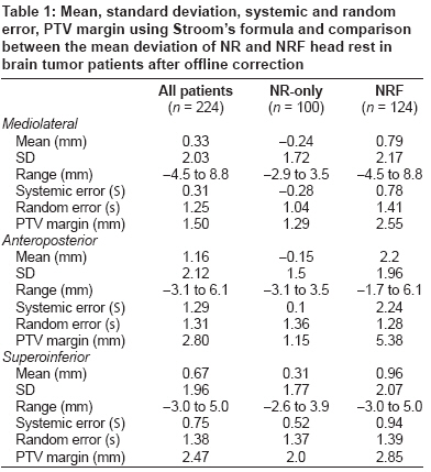
Translational displacements were measured in 224 (112 anterior and 112 lateral) portal images and were assessed in AP, ML, and SI directions. The mean total error in AP, ML, and SI directions was 1.16 mm (SD 2.12), 0.33 mm (SD 2.03), and 0.67 mm (SD 1.96), respectively. The setup errors in the AP, ML, and SI directions were normally distributed. The systematic error for all patients and each group is represented in [Table - 1] and the nomogram of mean displacement is shown in [Figure 2 A-C]. In all patients, systematic error from the anterior portal was 0.31 mm for the ML and 0.75 mm in the cranio-caudal directions. The mean systematic error for the AP direction in the lateral field was 1.29 mm. The random error in the ML direction was 1.25 mm, while it was 1.38 mm in the SI direction and 1.31 mm in the AP direction.
Neck rest (NR)-only group
The mean total error in the AP, ML, and SI directions was −0.15 mm (SD 1.5), −0.24 mm (SD 1.7), and 0.31 mm (SD 1.77), respectively. In the NR-only group, the systematic error was 0.1 mm in AP, 0.28 mm in the ML, and 0.52 mm in the SI directions. The random error in the ML direction was 1.04 mm, while it was 1.37 mm in the SI direction and 1.36 mm in the AP direction.
Neck rest with flexion (NRF) group
Translational displacements were measured in 124 portal images and were assessed in the AP, ML, and SI directions. The mean displacement in the AP, ML, and SI directions was 2.2 mm (SD 1.96), 0.79 mm (SD 2.17), and 0.96 mm (SD 2.07), respectively. The systematic error was 0.78 mm in the ML, 0.94 mm in the SI, and 2.24 mm in the AP directions. The random error was 1.41 mm in the ML, 1.28 mm in the SI, and 1.39 mm in the AP directions.
PTV margin calculation in all patients and in the different subgroups
CTV-PTV margins were calculated using the International Commission on Radiation Units and Measurements (ICRU) Report 62 [6] and Stroom′s [14] and van Herk′s [15] formulae [Table - 2]. In all patients, using the ICRU recommendation, the CTV-PTV margin in the AP, ML, and SI directions was 2.20 mm, 1.19 mm, and 1.72 mm, respectively. The corresponding values were 2.79 mm, 1.50 mm, and 2.47 mm with Stroom′s formula and 4.14 mm, 1.65 mm, and 2.84 mm with Van Herk′s formula. Thus, differential PTV margins may be required in different directions, with the maximum PTV margin required in the AP direction.
Comparison between different subgroups
In comparison with the NR-only group, the PTV margin was more in the NRF patients. The PTV margin with Stroom′s formula in the ML, AP, and SI directions was 1.29 mm, 1.15 mm, and 2.00 mm in the NR-only group and 2.55 mm, 5.38 mm, and 2.85 mm in the NRF group.
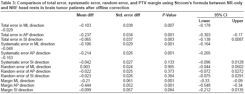
Comparison was done between the NR-only and NRF groups by independent t-test for total error, random error, systematic error in different directions. PTV margins were then generated by using Stroom′s formula [Table - 3]. There was significantly more total error in the NRF group in the ML and AP directions. In the ML direction, the mean difference in total error was −0.103 (95% CI: −0.178 to −0.029; P = 0.007); in the AP direction it was −0.237 (95% CI: −0.303 to −0.17; P = 0.001), and in the SI direction it was −0.065 (95% CI: −0.138 to −0.087; P = 0.083). In systematic error, a significant difference was seen in the ML and AP directions. However, there was no significant difference between the NR-only and NRF groups in random error in any direction. The PTV margin generated by using Stroom′s formula showed significant difference in the ML and AP directions. In the ML direction, the mean difference in PTV margin was −0.21 (95% CI: −0.33 to −0.09; P = 0.001) and in the AP direction it was −0.44 (95% CI: −0.54 to −0.34; P = 0.001). Thus, in the NRF group there was significantly more margin required in the AP and ML directions as compared to the NR-only group. The systematic error was significantly more in the NRF group in the ML and AP directions, but there was no significant difference in the random error between the groups.
Discussion
Advances in radiation therapy, such as 3DCRT and IMRT, aim to achieve a high dose differential between the target volume and surrounding normal tissues. 3DCRT involves careful delineation of the GTV as well as CTV. Though various studies have concluded that the CTV to PTV margin varies between 3-10 mm, [8],[9],[10],[11] it is important for each institution to develop its own data and protocol for growing margins using various immobilization devices. At our institution we have traditionally been giving a uniform margin of 5 mm for PTV in patients with brain tumors. The present study was done to evaluate the accuracy of our margin growing protocol using EPID and to ascertain the role of different head supports in margin generation for the PTV.
Various images like simulator film, first portal image, or DRR have been used as the reference image for comparing with the daily treatment. The advantage of simulator picture is that the quality of the picture is very good. However, it poses a problem especially for patients who are being planned for CRT, which may involve various steps like immobilization, CT scan, target volume delineation, data transfer, planning on the treatment planning system, and then the data transfer to the simulator. There could be errors induced during CT scans, laser alignment of CT, target volume delineation, observer noise, and interobserver variation. [16] In addition, there could be errors while transferring data from the planning system and also during plan implementation, which would contribute to the systematic errors. Any error in the above contributes to the systematic error and is missed if the simulator image is taken as the reference. Recently the Royal Marsden group has shown < 1 mm systematic error using customized neck rest and four-point fixation devices. [11] However, this data is based on the simulator images and therefore should not be used directly for complex CRT and IMRT for obvious reasons. DRR, which is constructed from the CT scan, takes into account errors at various steps, including that due to laser alignment, CT scan couch sag, data transfer to planning system and simulator to machine. But as the DRR is based on 5-mm CT slices, the quality of image is not very good. This was enhanced in our study by using various filters that are available on the image matching software. The use of the first portal image as the reference image should be discouraged as it cuts down all the systematic errors in the planning process. EPID has been considered more reliable than the portal films. [17]
In our study, EPI was compared with the DRR in all patients. For each patient 10-12 sets of images were evaluated. We have observed a total error of 0.33 mm in the ML direction, 1.16 mm in the AP direction, and 0.67 mm in the SI direction in this dataset. The systematic error was 0.31 mm in the ML, 1.29 mm in the AP, and 0.75 mm in the SI direction, while the random error was 1.25 mm in the ML, 1.31 mm in the AP, and 1.38 mm in the SI directions. Various margin generation recipes are available, of which the most commonly used are Stroom′s regimen and van Herk′s regimen. [13,15] Stroom′s formula is based on the probability of coverage of CTV after growing margin, while van Herk′s formula is based on normal tissue complication probability. In our study, the PTV margin using Stroom′s formula was 1.5 mm in the ML, 2.8 mm in the AP, and 2.47 mm in the SI direction. Thus the PTV margin of 5 mm, which is given routinely in our patients, appears adequate and could further be possibly reduced to 3 mm.
We have also compared setup errors with different head supports in this study. In patients with pituitary adenoma or tumors in the sellar/suprasellar region, flexion supports (NRF) were used to avoid critical structures like the eyes during planning. In patients with sellar/suprasellar tumors, 3DCRT planning may be done with a three-field non-coplanar beam arrangement. In this beam arrangement, two lateral fields and one vertex field with couch rotation is done. Though critical structures are better saved with this beam arrangement, couch rotation introduces one more uncertainty and also increases the treatment time. The same purpose may be served with flexion head support (NRF) without couch rotation.
Flexion devices have, however, led to increase in the setup errors in the ML and AP directions in our study. The total error in the ML direction was −24 mm with NR, while it was 0.79 with NRF. Of this total error, the random errors were comparable between the two groups, while the systematic error was significantly higher in the NRF group ( P = 0.001). Similarly, the total error in the AP direction was −0.15 mm in the NR-only group, while it was 2.2 mm in the NRF group ( P = 0.001). Even in the AP direction, the systematic component of the error was higher in the NRF group as compared to the NR-only group ( P = 0.001). While it appears that neck rest with flexion leads to uncertainty in the immobilization to some extent, the uncertainty had more of systematic component which may probably be due to the differences in the position on the CT scan as compared to that of the simulator where the plan was implemented. The random errors, on the other hand, were comparable between the NR-only and the NRF groups. The PTV margin of 2.5 mm for the NRF group in the ML direction was significantly higher than the 1.29 mm seen for the NR group ( P = 0.001). Similarly, for the AP direction, the PTV margin required for patients in the NRF group was 5.38 mm, while it was 1.15 mm for the NR group. Hence, differential margins in the AP and ML directions could be considered in future, especially in patients undergoing treatment with flexion supports.
One of the possible solutions to reduce these errors further is to use customized head rests for each patient. With the use of customized head rests, the Royal Marsden group has shown improved patient reproducibility. [18] Data regarding the use of more stable head supports in patients who require relatively small margins due to the close proximity of critical structures show decrease in errors with such techniques. [19],[20],[21],[22] Kumar et al . have studied the effect of the Gill-Thomas-Cosman relocatable frame on the reproducibility, using stereotactic radiation therapy (SCRT). [11] We feel that customized head rests should be used in order to decrease the systematic and random errors in these situations.
We have done offline correction when required and have an institutional protocol for ′no action′ or ′correction′ made on the basis of recent literature review. [23],[24] Our protocol was to take ′no action′ if the error between the portal image and DRR was less than 3 mm in any direction. In case of error of more than 3 mm, correction was done before the next treatment and repeat portal imaging was taken. However, in our experience, the offline correction was needed only on a few occasions and that too in the first 2 weeks of treatment. While online correction is recommended in high-precision techniques, it may not be possible in busy radiotherapy departments, especially when there are limited resources and a high work load, as is the situation in many countries. Therefore, after evaluating the results of the present study, we feel that offline correction can minimize the setup inaccuracies to acceptable limits and thus it is recommended for all patients who are being treated with high-precision radiotherapy techniques (CRT or IMRT). We have not studied interobserver variation during the process of matching the portal imaging with DRR. However, all the matching was done by a radiation oncologist (DD) and a technologist (BY) together, and the final matching had to be acceptable to both of them. In case of any discrepancy, the opinion of a third technologist or a radiation oncologist was sought. We have also not studied target volume delineation ′noise′ or interobserver variation in our study. Target volume delineation was done by a senior registrar and was counterchecked by a radiation oncologist (RJ), which is the routine protocol in our unit.
Conclusion Offline correction with electronic portal imaging reduces setup errors in patients undergoing treatment with high-precision techniques. A PTV margin of 5 mm appears to be adequate in the majority of the patients and further reduction in the margin to 3 mm may be considered in our set up. Neck support with flexion leads with significantly higher setup errors in the ML and AP directions. Differential PTV margin for the ML and AP directions may be considered for patients undergoing treatment with flexion supports.
References
| 1. | Langmack KA. Portal Imaging. Br J Rad 2001;74:789-804. Back to cited text no. 1 |
| 2. | Alheit H, Dornfeld S, Dawel M, Alheit M, Henzel B, Steckler K, et al . Patient position reproducibility in fractionated stereotactically guided conformal radiotherapy using the Brain Lab mask system. Strahlenther Onkol 2001;177:264-8. Back to cited text no. 2 [PUBMED] |
| 3. | Herman MG, Balter JM, Jaffray DA, McGee KP, Munro P, Shalev S, et al . Clinical use of electronic portal imaging: Report of AAPM radiation therapy committee task group 58. Med Phys 2001;28:712-37. Back to cited text no. 3 [PUBMED] |
| 4. | Humphreys M, Guerrero Urbano MT, Mubata C, Miles E, Harrington KJ, Bidmead M, et al . Assessment of a customised immobilisation system for head and neck IMRT using electronic portal imaging. Radiother Oncol 2005;77:39-44. Back to cited text no. 4 [PUBMED] [FULLTEXT] |
| 5. | ICRU Report 50. Prescribing, Recording and Reporting Photon Beam Therapy. International Commission on Radiation Units and Measurements, Bethesda: 1993. Back to cited text no. 5 |
| 6. | ICRU Report 62. Prescribing, Recording and Reporting Photon Beam Therapy (supplement to ICRU Report. 50) International Commission on Radiation Units and Measurements, Bethesda: 1999. Back to cited text no. 6 |
| 7. | Hurkmans CW, Remeijer P, Lebesque JV, Mijnheer BJ. Set-up verification using portal imaging: Review of current clinical practice. Radiother Oncol 2001;58:105-20. Back to cited text no. 7 [PUBMED] [FULLTEXT] |
| 8. | Jalali R, Budrukkar AN, Sarin R, Sharma D. High precision conformal radiotherapy in children and adolescents with brain tumours. Radiother Oncol 2005;74:37-44. Back to cited text no. 8 |
| 9. | Kalapurakal JA, Ilahi Z, Kepka AG, Bista T, Goldman S, Tomita T, et al . Repositioning accuracy with the Laitinen frame for fractionated stereotactic radiation therapy in adult and pediatric brain tumours: Preliminary report. Radiology 2001;218:157-61. Back to cited text no. 9 [PUBMED] [FULLTEXT] |
| 10. | Kortmann RD, Becker G, Perelmouter J, Buchgeister M, Meisner C, Bamberg M. Geometric accuracy of field alignment in fractionated stereotactic conformal radiotherapy of brain tumors. Int J Radiat Oncol Biol Phys 1999;43:921-6. Back to cited text no. 10 [PUBMED] [FULLTEXT] |
| 11. | Kumar S, Burk K, Nalder C, Jarrett P, Mubata C, A'hern R, et al . Treatment accuracy of fractionated stereotactic radiotherapy. Radiother Oncol 2005;74:53-9. Back to cited text no. 11 |
| 12. | Van Herk M, Remeijer P, Lebesque JV. Inclusion of geometric uncertainties in treatment plan evaluation. Int J Radiat Oncol Biol Phys 2002;52:1407-22. Back to cited text no. 12 [PUBMED] [FULLTEXT] |
| 13. | Stroom JC, de Boer HC, Huizinga H, Visser AG. Inclusion of geometrical uncertainties in radiotherapy treatment planning by means of coverage probability. Int J Radiat Oncol Biol Phys 1999;43:905-19. Back to cited text no. 13 |
| 14. | Stroom JC, Heijmen BJ. Geometrical uncertainties, radiotherapy planning margins, and the ICRU-62 report. Radiother Oncol 2002;64:75-83. Back to cited text no. 14 [PUBMED] [FULLTEXT] |
| 15. | van Herk M, Remeijer P, Rasch C, Lebesque JV. The probability of correct target dosage: Dose-population histograms for deriving treatment margins in radiotherapy. Int J Radiat Oncol Biol Phys 2000;47:1121-35. Back to cited text no. 15 [PUBMED] [FULLTEXT] |
| 16. | Weltens C, Menten J, Feron Bellon E. Interobserver variations in gross tumor volume delineation of brain tumors on CT and impact of MRI. Radiother Oncol 1998;48:14. Back to cited text no. 16 |
| 17. | Rosenthal SJ, Gall KP, Jackson M, Thornton A. Precision cranial immobilization system for conformal stereotactic fractionated radiation therapy. Int J Radiat Oncol Biol Phys 1995;33:1239-44. Back to cited text no. 17 |
| 18. | Weltens C, Kesteloot K, Vandevelde G, Van den Bogaert W. Comparison of plastic and Orfit masks for patient head fixation during radiotherapy: Precision and costs. Int J Radiat Oncol Biol Phys 1995;33:499-507 Back to cited text no. 18 [PUBMED] [FULLTEXT] |
| 19. | Willner J, Hadinger U, Neumann M, Schwab FJ, Bratengeier K, Flentje M. Three dimensional variability in patient positioning using bite block immobilization in 3D-conformal radiation treatment for ENT-tumors. Radiother Oncol 1997;43:315-21. Back to cited text no. 19 |
| 20. | Hess CF, Kortmann R, Jany R, Hamberger A, Bamberg M. Accuracy of field alignment in radiotherapy of head and neck cancer utilizing individualized face mask immobilization: A retrospective analysis of clinical practice. Radiother Oncol 1995;34:69-72. Back to cited text no. 20 |
| 21. | Boda-Heggemann J, Walter C, Rahn A, Wertz H, Loeb I, Lohr F, et al . Repositioning accuracy of two different mask systems-3D revisited: Comparison using true 3D-3D matching with cone-beam CT. Int J Radiat Oncol Biol Phys 2006;66:1568-75. Back to cited text no. 21 [PUBMED] [FULLTEXT] |
| 22. | Gilbeau L, Octave-Prignot M, Loncol T, Renard L, Scalliet P, Greβgoire V. Comparison of setup accuracy of three different thermoplastic masks for the treatment of brain and head and neck tumors. Radiother Oncol 2001;58:155-62. Back to cited text no. 22 |
| 23. | Pisani L, Lockman D, Jaffray D, Martinez A, Wong J. Setup error in radiotherapy: On-line correction using electronic kilovoltage and megavoltage radiograph. J Radiat Oncol Biol Phys 2000;47:825-39. Back to cited text no. 23 |
| 24. | Boer H, Heijmen B. A protocol for the reduction of systematic patient setup errors with minimal portal imaging workload. Int J Radiat Oncol Biol Phys 2001;50:1350-65. Back to cited text no. 24 |
Copyright 2008 - Journal of Cancer Research and Therapeutics
The following images related to this document are available:
Photo images
[cr08020t3.jpg]
[cr08020f2.jpg]
[cr08020f1.jpg]
[cr08020t1.jpg]
[cr08020t2.jpg]
|
