 |
| About Bioline | All Journals | Testimonials | Membership | News |
|
||||||
|
||||||
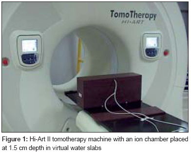
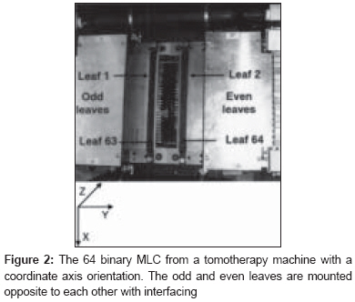
Journal of Cancer Research and Therapeutics, Vol. 4, No. 2, April-June, 2008, pp. 88-90 Brief Communication Multileaf collimator transmission from the first Hi-Art II helical tomotherapy machine in India Kinhikar RajeshA Department of Medical Physics, Tata Memorial Hospital, Parel, Mumbai Code Number: cr08023 Abstract The purpose of this study was to measure the multileaf collimator (MLC) transmission from the first Hi-Art II tomotherapy machine installed at the Advanced Center for Treatment, Research, and Education in Cancer (ACTREC). The MLC transmission was measured with an A1SL ion chamber and the radiographic extended dose range (EDR2) film in virtual water slabs at 1.5-cm depth with a source-to-surface distance of 85 cm. The MLC transmission was measured for 30 s with all leaves open and for 360 s with all leaves closed. The movable jaws were set to the calibration field size of 5 × 40 cm at isocenter. The MLC transmission was found to be 0.3% with the ion chamber and 0.32% with the film. Thus, the MLC transmission value was found well within the manufacturer tolerance of 0.5%. MLC can safely be used for the beam modulation during intensity-modulated radiotherapy (IMRT) to deliver accurate doses to the patients. Keywords: Film, ion chamber, multileaf collimator transmission, tomotherapy Helical tomotherapy represents a new approach to intensity-modulated radiation therapy (IMRT). [1],[2],[3],[4],[5],[6] IMRT requires stringent modulation from the multileaf collimators (MLC). Patient leakage dose from helical tomotherapy results from two sources: Leakage through and between closed MLC leaves and from the jaws. The leakage from the MLC should be exactly measured and modeled in the treatment planning system to accurately deliver the desired doses to the patients. Recently, the first tomotherapy machine (Tomotherapy Inc, Madison, WI) was installed at the Advanced Center for Treatment, Research, and Education in Cancer (ACTREC). Acceptance test procedures and the dosimetry were performed for commissioning the tomotherapy machine. The purpose of this study is to report the estimate of the MLC transmission from tomotherapy. Materials and Methods Hi Art II tomotherapy machine Multileaf collimators Transmission with static measurements An extended dose range (EDR2) film was placed at 1.5-cm depth and centered under the MLC. The film was irradiated for 4 s with all leaves open for the same field size of 5 x 40 cm. Later, the film was irradiated for 360 s with all leaves closed. The films were digitized in a 16-bit Vidar film scanner to find out the mean pixel value from each film. The ratio of the mean pixel value with the leaves closed to the value with the leaves open gave the MLC transmission as measured with the EDR2 film. Results The average MLC transmission measured with the ion chamber was found to be 0.3% (specifications 0.5%). This result was further supported by the EDR2 film measurements. The mean pixel value for the film with all leaves open for 4 s was 24357. Thus the mean pixel value per second was 6088. The mean pixel value for the film with all leaves closed for 360 s was 7136, thus giving 19.8 as the pixel value per second. The MLC transmission was calculated from the ratio of the mean pixel value per second with all leaves closed to that of the value with all leaves open. The film measurements showed good agreement with the ion chamber measurement as well. The average transmission was 0.32%. Discussion This study deals with the MLC transmission from a 6-MV tomotherapy photon beam. MLC transmission [9],[10],[11],[12],[13],[14] is an important and contributory factor since it is directly used by the treatment planning system as the modulation factor (MF). [8] MF is defined as the maximum leaf open time divided by the average leaf open time for those leaves that do open during a treatment. The MF is a user-definable treatment optimization parameter that usually has a value between 1.2 and 3.5. The instantaneous leakage through closed MLC leaves would be multiplied by a factor of 3.5 for those patient plans with a 3.5 modulation factor. It would be multiplied by 2.5, on average, for those leaves that do open since there would not be leakage when those leaves are open. The average MF used by helical tomotherapy patients is less than 2.0. The overall beam-on time increase for helical tomotherapy equals the MF multiplied by the number of slices treated. The MLC transmission from the film depicted the tongue-and-groove effect, while the ion chamber measurements could record a transmission at a given point. The measurements carried out with in this study were also compared with the MLC transmission from linear accelerators at our center. The average MLC transmission for Varian and Siemens linear accelerators was estimated to be 1.9% and 1.5%, respectively, of the open 10 x 10 cm 2 field at isocenter for the 6-MV photon beam. The thickness of Varian and Siemens MLC is 7.2 cm and 7.6 cm, respectively. The MLC from tomotherapy is 10 cm thick. The fact is that the average MLC transmission from tomotherapy was estimated to be 0.3 and 0.32 with the ion chamber and the film, respectively. The film measurements actually depicted the interleaf as well as intraleaf MLC transmission. In linear accelerators, for measurement of MLC transmission, the monitor units (MU) settings for closed leaves are much higher (10-20 times) than for open leaves. This is to increase the intensity and distribution statistics of the transmitted X-rays collected either by the ion chamber or the film. In tomotherapy, one cannot set the MU directly; rather, only exposure duration can be controlled. Hence, the exposure time of 360 s was used for measurement of MLC transmission with leaves closed. This exposure time, compared to the 4 s for open leaves, was as much as 90 times higher. This could again be justified by the 10-cm thick MLC from the tomotherapy which sufficiently attenuates the primary beam. Secondly, a standard procedure for this measurement was followed as per the manufacturer′s guidelines. The measured MLC transmission that resulted from this work was clinically acceptable for safe delivery of IMRT with tomotherapy. Conclusion Helical tomotherapy is a new modality of radiation therapy treatment delivery. The machine delivers highly conformal intensity-modulated fields in a helical fashion. Film dosimetry, coupled with point dose measurements with an ion chamber are the tools available at this point for dosimetric verification of the machine characteristics, including MLC transmission. The tomotherapy machine can safely be used for IMRT delivery with a minimal MLC transmission.References
Copyright 2008 - Journal of Cancer Research and Therapeutics The following images related to this document are available:Photo images[cr08023f2.jpg] [cr08023f1.jpg] |
| |||||||||
