 |
| About Bioline | All Journals | Testimonials | Membership | News |
|
||||||
|
||||||
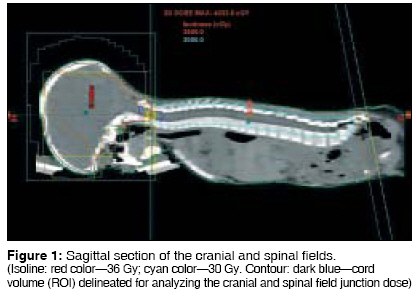
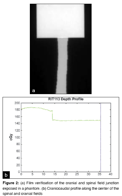
Journal of Cancer Research and Therapeutics, Vol. 5, No. 2, April-June, 2009, pp. 113-115 Brief Report A simple technique for cranio-spinal irradiation in pediatric patients Prabhakar R, Haresh KP, Munshi A, Sridhar PS, Subramani V, Julka PK, Rath GK Department of Radiation Oncology, Institute Rotary Cancer Hospital, All India Institute of Medical Sciences, New Delhi Code Number: cr09028 DOI: 10.4103/0973-1482.52799 Abstract Purpose: Field matching poses challenges in craniospinal irradiation (CSI) as it leads either to underdosage or overdosage in the junctional area. A simple technique for CSI in pediatric patients is proposed.Materials and Methods: Computed tomography scans were performed in the prone position. Two lateral cranial fields and a direct posterior spinal field were planned with a common central axis. Half-beam-blocked cranial fields with zero collimator rotation were used for treating the cranium. A half-beam-blocked field defined with jaws was used to treat the spinal column at an extended source-to-surface distance. Before treating the patient, matching of the cranial and spinal field junction along the central axis was verified with an extended dose range film. Results and Conclusion: The technique described is simple and easy to implement and can be applied to pediatric patients undergoing CSI. This method has the potential to reduce daily setup time and setup errors. This technique is ideally suitable for patients with spinal fields less than 30 cm. Keywords: Craniospinal irradiation, field-junction, medulloblastoma, radiotherapy Introduction Cranio-spinal irradiation (CSI) is a complex and an important technique in the treatment of malignancies such as medulloblastoma involving central nervous system. Several methods have been defined to deliver CSI. [1],[2],[3],[4],[5],[6],[7] The implementation of CSI requires at least one junction between the orthogonal cranial and spinal radiation fields. CSI can be performed either in a prone or supine position. Treating the patient in a prone position has the advantage of visualizing the junction between the spinal and cranial fields. However, the effort and time involved in matching the cranial and spinal fields lead to discomfort for the patient. Hence many techniques have been proposed that treat the patient in a supine position. Treatment in this position leads to difficulty in visualizing the field junction(s) where setup errors may creep in. Field matching always poses difficultly in CSI as it either leads to underdosage or overdosage in the junctional area. [8] In this paper, we propose a simple technique for CSI in young pediatric patients which overcomes the problem of field matching.Materials and Methods An important aspect of CSI technique is the immobilization of the patient during treatment. Ten pediatric patients who had to be treated with CSI were taken into the study. The age ranged from 3 to 7 years. Patients were positioned with Vac-loc TM in a prone position and the head was immobilized by a thermoplastic cast on a prone head rest. A planning computed tomography (CT) scan was done in the prone position with 5 mm slice thicknesses on a Siemens volume zoom TM CT scanner. The CT datasets were transferred to the Eclipse treatment planning system (Varian Medical System TM ). The critical structures, clinical target volume (CTV), and the body contour were delineated in the planning system. Two lateral cranial fields and a direct posterior spinal field were used with a common central axis. For the cranial region, parallel opposed fields were used with half beam block provided by asymmetric jaws, with the central axis at the caudal edge of the field. The collimator rotation was set as zero to match the superior border of the spinal field. In the case of spinal field, a half-beam-blocked field was defined with jaws and used to treat the spinal column at an extended source-to-surface distance (SSD) of 150 cm to cover the S2 vertebrae. Before starting treatment with this technique, any shift in the central axis point at 100- and 150-cm SSD was checked and corrected. The vertical axis of the couch should be perfect and there should not be any sag in the couch. The dose calculated in the treatment planning system should be verified with the actual measurement before delivering at an extended SSD for spinal field. For treating the spinal field, the gantry should be brought to the head top position (gantry = 0°) and the couch should be brought vertically down. The field length has to be opened to the desired position to treat the spine by asymmetric jaws. The jaw positions for the cranial and spinal fields were as follows. Cranial field-Y2 jaw was opened to cover the entire skull keeping Y1 = 0. Spinal field-Y1 was opened to cover the S2 junction and Y2 = 0 (IEC 1217). A multileaf collimator was used to shield the normal structures in the cranial and the spinal fields. In order to reduce the hotspots inside the cranial field, especially at thin regions, a field-in-field technique was used. The cranium was treated to a dose of 36 Gy in 20 fractions over 4 weeks and the spine with a dose of 30 Gy in 20 fractions over 4 weeks with 6-MV X-rays. Subsequently, the primary tumor was given an additional boost to a dose of 20 Gy in 10 fractions over 2 weeks. In the planning system, doses were prescribed to the reference points placed in the cranial and spinal fields. The reference point for the spinal field was placed at the anterior aspect of the spinal cord and the dose was prescribed to 95% isoline. The variation of dose in the entire cord as well as in a block of cord (region of interest-ROI) which is 1.5 cm caudal and 1.5 cm cephalad to the craniospinal junction was also analyzed. Before implementing this technique, matching of the cranial and spinal field junction along the central axis was verified with an extended dose range (EDR2) film. The EDR2 was initially calibrated (parallel or perpendicular method) and calibrated data were fitted to the exposed cranial and spinal fields, and the exposed film was analyzed with the RIT software (RIT Software Ltd., Bulgaria). Results [Figure - 1] shows the cranial and the spinal field summed together in the sagittal section with isodose curves. [Figure 2a] shows the cranial and spinal fields exposed on an EDR2 film. It clearly displays the matched cranial and spinal field junction. The figure basically depicts the above two fields exposed on an EDR2 film which is placed perpendicular to the central axis of the beam at a 0° gantry angle in a virtual water phantom at their respective SSDs. [Figure 2b] shows the longitudinal profile of the cranial and spinal fields. In our study, the median dose to the whole spinal cord ranged between 31.4 and 32.6 Gy for the studied 10 patients. The median dose to the ROI ranged between 31.0 and 35.8 Gy (half of ROI lies inside the cranial 36 Gy and other half inside the spinal 30 Gy isoline). The mean minimum dose was 28.9 ± 0.5 Gy (range: 28.1-29.1 Gy) and 29.1 ± 0.6 Gy (range: 28.1-29.7 Gy) for the entire cord and the ROI, respectively.Discussion CSI is a complex radiotherapeutic technique because of the challenges involved in delivering a uniform dose to the brain and the spinal axis, taking care of the junctions involved. The maximum field size in Clinac 2300 C/D is 40 x 40 cm at a 100cm SSD. To cover a spinal field of 30-cm length on the patient skin surface in the prone position, the couch was lowered to a 150cm SSD. An important aspect of this technique is the verification of field matching at 100 and 150cm SSDs. Matching of the cranial and spinal field junction is necessary only when this technique is implemented for the first time. If there is any mismatch between the two fields, then the jaws can be closed or opened accordingly so that both of them match exactly. This ensures that there is no hot or cold spot at the field junction. In the case of cranial field, to reduce the hot spots inside the cranial field, a simple field-in-field technique may be employed as shown in [Figure - 1]. The daily setup time required for the treatment was considerably reduced with this technique. It may vary from 3 to 5 minutes and depends upon the cooperation of the patient. The biggest advantage with our technique is that there is only one manual movement (which is lowering of the treatment couch apart from gantry rotation) that is needed for the setting of the spinal field after treating the cranial field. Hence there is very less chance for setup error to creep in. In the case of moving junction technique, the patient needs to be reset to the new isocenter for the spinal fields, and the technologist has to manually ensure the matching of the cranial and spinal field junction which is not required in our method. The mean minimum cord dose variation within the ROI in our study was 3% (range: 1-6.3%) as compared to 6% (0.3-14%) in moving junction technique. [9] Patients with a spinal field less than 30 cm from C2-C3 junction to the lower border of S2 vertebrae are ideally suited for this technique. Conclusion The technique described is simple and easy to implement and can be applied to pediatric patients undergoing CSI. It avoids the problems associated with the junction in treating CSI and reduces the overall setup time required for treating the patient.References
Copyright 2009 - Journal of Cancer Research and Therapeutics The following images related to this document are available:Photo images[cr09028f2.jpg] [cr09028f1.jpg] |
| |||||||||
