
|
Journal of Applied Sciences and Environmental Management
World Bank assisted National Agricultural Research Project (NARP) - University of Port Harcourt
ISSN: 1119-8362
Vol. 7, Num. 2, 2003, pp. 78-88
|
Journal of Applied Sciences & Environmental Management, Vol. 7, No. 2, Dec, 2003, pp. 78-88
Object Oriented Software Development Using a use-cases Approach
1Okerinde J B; *2Owolabi, O
1Information Technology Department, Shell Petroleum Development Corporation, Port Harcourt, NIGERIA
2Dept. of Mathematics/Computer Science, Faculty of Science, University of Port Harcourt, P. M. B. 5323, Port Harcourt Nigeria
* Corresponding author
Code Number: ja03024
ABSTRACT:
This paper presents a systematic approach to the analysis and design of an online banking system using the Use-Cases method of Jacobson. This analysis and design method will support the development of highly effective reuseable code, thus bringing the benefits of object orientation into important software projects @ JASEM
The Object-oriented systems development methods differ from the traditional development techniques in that the traditional techniques view software as a collection of programs (or functions) and isolated data. A program, according to Wirth (1975), is "a set of mechanisms for performing certain action on certain data". The object-oriented approach, on other hand, insists that such approaches result from an artificial view of the "real world" (OSM, 1999). Data and processes cannot be considered in isolation as each depends on, and contributes to, the other. Object orientation considers the "real world" as comprising a number of "objects" each of which encapsulates data and processing elements into a single "entity" (an object is commonly an entity in data modeling terms). It is a combination of the process and the data oriented approaches to system development. As such it represents a major advance in our ability to model systems, making their implementation far closer to a direct simulation of the real world. The development of object orientation has been driven largely by the basic principles of modularity, particularly the ability to decompose things into self contained, highly cohesive modules which can be combined in limitless ways to provide a large variety of system solutions. To put it another way, objects are identified, implemented and reused as required. This has given rise to the concepts of the "Software IC" which treats the software components of a system in a similar way to "off the shelf" integrated circuits for hardware systems. Thus an attempt is made to make software development easier and more natural by raising the level of abstraction to the point where applications can be implemented in the same terms in which the users describe them. However, it must be appreciated that real reusability has to be worked for and doesn't just happen. So far, most of the work on object orientation has concentrated on the development of objects at the Design/Implementation level, but the same object oriented principles must be applied as well to the analysis level in order to ensure that the "real" objects and their references are consistently implemented. We therefore emphasize in this paper a method, the use-case method (Jacobson, 1994), of object oriented analysis.
Object Oriented Software Development: System development can be viewed as a process; the development itself is a process of change, transformation, or addition to an existing product. The process can be divided into sub-processes: small, interacting phases, that must be so clearly defined in such a way that allows each activity to be performed as independently as possible. Each subprocess must possess the following (Anderson and Bergstrand, 1995);
- A description in terms of how it works;
- Specification of the input required for the process;
- Specification of the output to be produced;
This process can be viewed in terms of the Analyse-Design-Implement model:
Analysis translates the users' needs into system requirements and functionality.
Design begins with a problem statement and ends with a detailed design that can be transformed into an operational system. This step constitutes the bulk of the software development activity that includes the definition of how to build the software.
Implementation refines the detailed design into the system development that will satisfy the users' needs. It includes the system development, and its testing.
In procedural programming, a designer examines the entire problem to be solved and proceeds to break the big problem into smaller pieces that can be solved algorithmically, i.e., by a specific set of steps. After variables are declared, the specified sequence of actions is followed. The program and the data are viewed as separate entities. In the object-oriented approach, on the other hand, a designer views the system to be implemented as a set of interacting objects. So, to code a system in object-oriented paradigm, the programmer defines objects and associated properties. The sequence of actions that occur in the running system depends on how the user interacts with the objects.
When developing an object-oriented application, two basic questions always arise:
- What objects does the application need?
- What functionality should those objects have?
For example, every Windows applications needs window objects that can either display something or accept input. Whenever a window displays something, that something is an object as well. Conceptually, each object is responsible for itself e.g. a window object is responsible for things like opening, sizing and closing itself. Programming in an object-oriented system consists of adding new kinds of objects to the system and defining how they behave.
In the Object Oriented Paradigm, the problem domain is modeled using object-classes, and instances of the objects (Booch, 1994). An object is any abstract or real world item that is relevant to the system. An object-class is a grouping of these objects. For example, in a library information system object-classes would be such things as members, books, etc. Objects would be instances of these classes.
The object-oriented software development life cycle consists of three processes: object-oriented analysis, object-oriented design, and object-oriented implementation as shown in Figure 1.
Object-oriented Analysis
The first task in Object-Oriented analysis is to find the class of objects that will compose the system. At the first level of analysis, we can look at the physical entities in the system, that is, who are the players and how do they cooperate to do the work of the system? These entities could be individuals, organizations, machines, units of information, or whatever else makes sense in the context of the real-world system. In the process of developing a model, the objects that emerge can help in establishing a workable system. The following are clues for finding the candidates classes and objects:
Persons: What roles does a person play in the system? For example, customers, employees, of whom the system needs to keep track.
Places: These are physical locations, buildings, stores, sites or offices about which the system keeps information.
Things or event: These are events, points in time that must be recorded. For example, the system might need to remember when a customer makes an order, therefore an order is an object.
To understand the system requirement, users or the actors should be identified. The concept of use-case was suggested by Jacobson (1994) to describe the user-computer interaction.
The next thing to do is to identify the hierarchical relationship between super-classes and subclasses before identifying the attributes (properties) of objects, such as name, sex and age.
Object-Oriented Design: The goal of the object-oriented design (OOD) is to design the classes identified during the analysis phase and the user interface. Additional objects and classes that will support the implementation of the requirements are also identified at this stage. For example, the object that will be required for the user interface such as data entry window.
Object-Oriented Implementation: After the object-oriented analysis and design, it is important to construct a prototype of some of the key components of the system. A prototype is a version of the software product developed in the early stages of the product's life cycle for specific, experimental purposes. Since object-oriented development is highly incremental, the users' feedback from the prototype is used to further analyse and design the system until the user is fully satisfied with the system or their requirement is met before implementation is done.
ANALYSIS, DESIGN AND IMPLEMENTATION OF AN ONLINE BANKING SYSTEM
Mobile Link Online Banking System Description: n this case study, the Object-Oriented system development methodology will be used in the analysis, design and implementation of Mobile Link Online Banking system. Online banking systems have recently become very important due to the central role of electronic banking in the new e-commerce era (Bahrami, 1999; Winfield, 2001). The system description is as follows: The Mobile Link bank client must be able to deposit an amount to and withdraw an amount from his/her accounts from any 'Cash Machine' of the bank in any location. Each transaction must be recorded, and the client must be able to review all transactions performed against a given account. Recorded transaction must include the date, time, transaction type, amount, and account balance after the transaction. A Mobile Link bank client can have two types of accounts: a current account and a savings account. For each current account, one related savings account can exist. Access to the MobileLink bank accounts is provided by a password (for personal identification). A password should allow access to all accounts held by the bank client. Neither a current nor a savings account can have a negative balance. The system can automatically withdraw money from a related savings account if the requested withdrawal amount on the current account is more than its current balance. If the balance on a savings account is less than the withdrawal amount requested, the transaction will stop and the bank client will be notified.
Object-Oriented Analysis for the Mobile Link Online Banking System: The concept of use-case (Jacobson, 1994), the user-computer system interaction, is adopted in this work. Use-case is a typical interaction between a user and a system that captures users' requirement and needs. Expressing this high-level process and interaction with the potential system users in a scenario and analyzing it is referred to as use-case modeling. Scenarios are used to examine who does what in the interactions among objects and what role they play. This interaction among objects' roles to achieve a given goal is called collaboration. The Object Oriented Analysis (OOA) consists of the following steps: identify the actors, develop a business model using activity diagram, develop the use-cases, develop interactive diagrams and identify classes.
We shall follow the OOA steps listed above for the MobileLink Banking System analysis
· Actors for the MobileLink Online Banking System
The bank system will be used by one category of users, which will be known as bank client throughout this case study. Therefore the actor of the system is the bank client. The bank client must be able to deposit an amount to and withdraw from his/her accounts using the system.
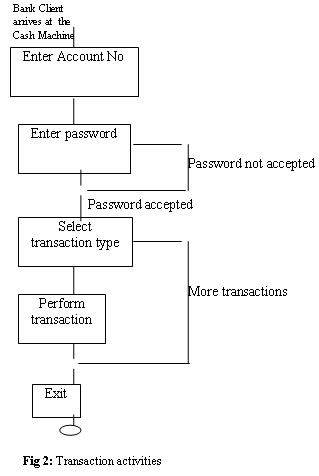
Business Process model for the MobileLink Banking System
A simple activity diagram for the online banking system starts from the bank client point of arrival at the cash machine or ATM as shown in the Fig 2. For any banking transaction using the online banking system, the bank client will be required to carry out the following activities; perform approval process, enter bank customer number, enter password, select type of transaction, ask type of transaction, enter type of transaction, perform transaction, end transaction
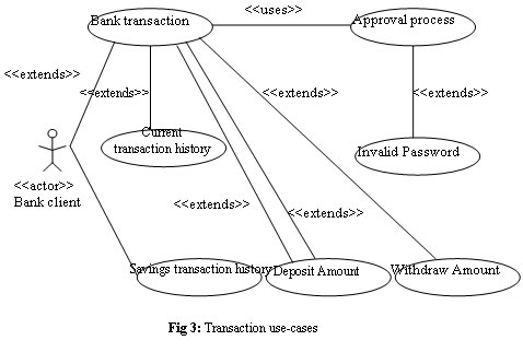
Use-Cases for the Mobile Link Banking System
The following use-cases, modeling the interactions between the actor (the bank client) and the bank, are created from the system requirements, review of existing or manual system documentation, interview, and observations:
1. Bank Transaction : The bank clients interact with the bank system by going through the approval process after which the bank client can perform a bank transaction.
2. Approval Process : The bank client enters a password. The activities for the Approval process use-case are: Enter Password and Verify Password.
3. Invalid Password : If the Password is not valid, an appropriate message will be displayed to the client. This use-case extends the approval process.
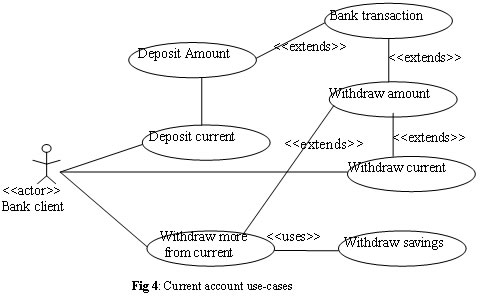
4. Deposit amount : The bank client interacts with the bank system after the approval process by requesting to deposit money to an account. The client selects the account for which a deposit is going to be made and enters an amount. Steps involved are: Request account type, Request deposit amount, Enter deposit, Insert cash.
5. Deposit Savings : The client select savings account for which deposit is going to be made, following same step as in deposit amount use-case.
6. Deposit Current : The client select current account for which deposit is going to be made, following same step as in deposit amount use-case.
7. Withdraw amount : The bank client interacts with the bank system after the approval process by requesting to withdraw money from an account. This use-case extends the bank transaction use-case. Steps involved are: Request account type, Request withdrawal amount, Verify sufficient, Eject cash.
8. Withdraw Savings: The client tries to withdraw an amount from a savings account. If the amount is less than or equal to the balance, the action is performed on the savings account.
9. Withdraw Current: The client tries to withdraw an amount from a current account. If the amount is less than or equal to the balance, the action is performed on the current account.
10. Withdraw more from Current: The client tries to withdraw an amount from his/her current account. If the amount is more than the current account balance, the difference is withdrawn from the related savings account. This use-case extends the withdraw amount use-case.
11. Withdraw Savings denied: The client tries to withdraw an amount from a savings account. If the amount is more than the balance, the transaction is halted and a message displayed. This use-case extends the withdraw amount use-case.
12. Savings Transaction History: The client requests a history of transactions for a savings account. The system displays the transaction history for the savings account. This use-case extends the bank transaction use-case.
13. Current Transaction History: The client requests a history of transactions for a current account. The system displays the transaction history for the current account. This use-case extends the bank transaction use-case.
The extends association is used when we have a use-case that is similar to another use -case but does a bit more. For example, the Withdraw current use-case extends the Withdraw amount use-case. The Withdraw amount use-case represents the general case of withdrawal from any type of account. The withdraw current now accounts for the peculiarities of a current account withdrawal. Same is true for the withdraw savings use-case.
The uses association occurs when a behaviour is common to more than one use-case and we want to avoid repetition of description of behaviour. For example, the Approval process use-case is used by the Bank transaction use-case.
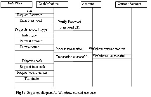
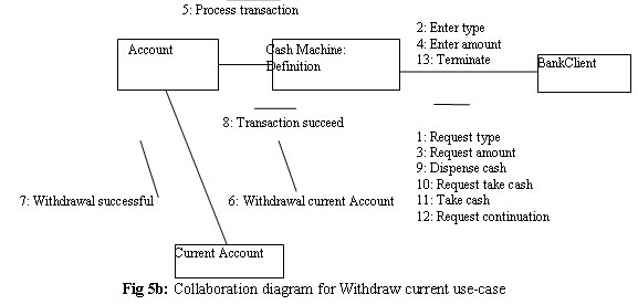
The scenarios for the Transaction and the Current account use-cases are shown in Figures 3 and 4. These scenarios will have to be constructed for all the uses-cases listed.
Classes for the Mobile Link Banking System: Identification of classes has been described as the hardest part of object-oriented analysis and design. In fact, it is almost impossible to speak of a perfect class structure or the right set of objects (Booch, 1994). This section documents the identification of the classes for the Mobile Link Banking System using the use-case driven approach. To identify the objects of a system, we need to analyse the lowest level of the use-cases with sequence and collaboration diagrams. Sequence and collaboration diagrams represent the order in which things occur and how the objects in the system send messages to one another. The sequence and collaboration diagrams for some of the uses cases identified above are shown in Figs. 5a and 5b. Using the sequence and collaboration diagrams, the following classes can been be identified for the Mobile Link online banking system: Bank class: belongs to the Bank. It is the repository of accounts and process of the account's transactions. Bank Client class: an individual that has a current account or a savings account. Cash Machine class: allows access to all accounts held by a bank client. Account class: an abstract class; it defines the common behaviors that can be inherited by other classes such as Current Account and Savings Account.
Transaction class: keeps track of transaction, time, date, type, amount, and balance
Current Account class: models clients' Current Account that allows special online withdrawal.
Savings Account class: models a client's savings account
Relationships, Attributes and Methods for the MobileLink Banking System:
Relationships:
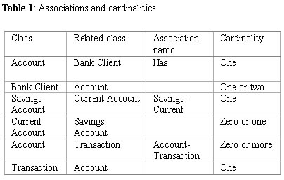
Every object in a system interacts and relates to others that rely on it for services and control. The associations and their cardinalities in the MobileLink system are shown in table 1.
Attributes:
Attributes are things an object must remember such as color and cost. To understand attributes we must understand the system's responsibilities by developing use-cases.
By analysing the use-cases for the system, the following attributes can be identified for the established classes:
Bank class: Branch and Address
BankClient class: firstName, lastName, customerNumber, password and account
CashMachine class: address and state
Account class: number, balance, bankClient and transaction
Transaction class: transID, transTime, transType, amount, postBalance
CurrentAccount class: derives attributes from Account (superclass)
SavingsAccount class: derives attributes from Account (superclass)
Methods:
Objects not only describe abstracts data but also must provide some services. Methods and messages provide services in object-oriented systems. Methods can be used to print an object, initialise variable or do some calculations. Every class is responsible for storing methods that will be used to manage its attributes.
For example, the account object must be able to create transaction records of deposit or withdrawal operation a bank client perform on an account. From the sequence diagrams, we can identify methods for each class in the MobileLink Banking System as follows:
Bank class:
BankClient class:
Verify Password ( ), to verify the client's password.
Account class:
Deposit ( );
Withdraw ( ); to be able to withdraw insufficient amount from the savings account;
Create transaction ( );
UpdateAccount ( );
SavingsAccount class:
Withdraw ( );
RetrieveAccount ( );
UpdateAccount ( );
CurrentAccount class:
RetrieveAccount ( );
UpdateAccount ( );
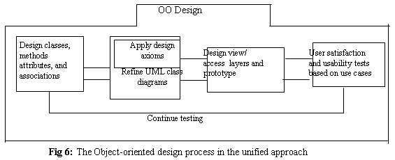
Object-Oriented Design for Mobile Link Banking System: The processes involved in the Object-oriented design phase are shown in fig 6. Attributes design: Identification of attributes in the object-oriented system analysis are done in the design phase in preparation for implementation. The main goal of this phase is to refine and define in detail the identified attribute and methods for the system. Attributes represent the state of an object. When the state changes, the changes are reflected in the values of the attributes. An attribute can be single-valued or multi-valued with several values at a point in time (Nornman, 1996). A multi-valued attribute can be used, for example, to keep tract of customers that have visited a website. A third type of attribute is the reference attribute which models association. For example, a client may have one or more bank accounts i.e. a client has zero to many instances of Account.
The Unified Modeling Language (UML) format for describing attributes is: visibility name : type-expression = initiated value where; visibilty could be + for public (accessibility to all classes) # protected (accessibility to subclasses and methods of the classes) - private (accessibility only to methods of the class) type-expression is the type of attribute such as string or float ; initial-value is the initial value for the object. For example,.+custNumber:string = 1000
A complete UML class diagram showing the classes of the MobileLink System with their attributes and methods as well as the interactions between the classes is shown in Fig 7.
Methods design: The next step in the object-oriented design is the design of methods identified in the analysis phase. The algorithms for the methods are specified. Like the attribute, the by UML format for describing a method is: visibility name (parameter list): return type-expression where parameter-list is a list of parameters, separated by commas return-type-expression is a value to be returned by the method.
For example, +getNmane():aName
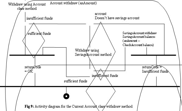
The activity diagrams for some of the methods identified above are shown in Figs. 8 and 9.
The activity diagram in Fig. 8 describes the verifyPassword method in detail. A bank client Customer number and password are sent from the Cash Machine object and used as argument in the verifyPassword method. The verifyPassword method will create a bank client object and attempt to retrieve the client data based on the supplied customer number using the retrieveClient method.
Fig 9 shows the current account specific withdrawal method. It handles the possibility of withdrawing excess funds from an associated savings account. User Interface Design for Mobile Link Online Banking System.
The next step is to design the user interface for the banking system. This will enable bank clients to do their banking from any of the banks' cash machine.
On displaying the MainUI, the client can then select from any of the following services;
File: Exit the system by selecting exit option from the File menu;
Current: Deposit into the current account by selecting the Deposit option, withdraw into the current account by selecting the Withdraw option;
Savings: Deposit into the savings account by selecting the Deposit option, Withdraw into the savings account by selecting the Withdraw option;
Balance: Account balance and transaction history can be viewed by selecting the transaction history from the Balance menu.
Object-Oriented System Implementation: Implementation is the last phase in Object-oriented system development. It involves using any programming language (such as Borland C++, Visual C++, etc. that support object-orientation) for the coding. Then follows system quality testing and user acceptance testing. An object-oriented database management system (OODBMS) is also required to enable the creation and maintenance of data. The OODBMS can be used for object definition, object manipulation and recovery. It allows objects to interact with other objects; objects are 'active' components in the object-oriented database, unlike the conventional database system where records play a 'passive' role. Modern databases are distributed databases, which implies that portions of the database reside on different computers in a network. Each portion of the system is managed by a server, that is, a process responsible for controlling access and retrieval of data from the database.
RESULTS
The result of this analysis and development exercise has been the derivation of a class hierarchy suitable for an object oriented implementation, given a description of the requirements of a mobile banking software system. The utility and effectiveness of the use-cases approach for such a system development exercise has been demonstrated. This approach will support a smooth transition from system analysis and design through to the final code.
REFERENCES
- Anderson, M. & J. Bergstrand (1995). Formalising Use-Cases with Message Sequence Charts. Masters thesis, Department of Communication Systems at Lund Institute of Technology, Sweden.
- Aoki, A (1993). "Objecto shikou shi sutemo bunseki sekkei nyuumon (Introduction to object-oriented analysis and design)". Tokyo: Software Research Associates, Inc, Japan.
- Bahrami, A. (1999). Object Oriented Systems Development Using the Unified Modeling Language. Irwin/McGraw-Hill, U.S.A.
- Booch, G.(1994). Object-Oriented Design with Applications. Second Edition. The Benjamin/Cummings Publishing Company, Inc, Menlo Park, CA.
- Herbseb, JD, Klein, H, Oslon, GM, Brunner, H, Oslon, JS, and Harding, J (1995). "Object-Oriented Analysis and Design in Software Project Teams." J. Human-Computer Interaction, 10, 249-292.
- Howitz, D (1992). "Bringing objects to mainstream MIS." Object Magazine, 2(4) 1992.
- Jacobson, I (1994). Object-Oriented Software Engineering: A use-Case Driven Approach. Addison-Wesley, Reading, Object Technology Series, MA.
- Khoshafian, S (1990). Insight into object-oriented databases. J. Information and Software Technology, 32 (4).
- Norman, R (1996). Object-Oriented Software Analysis and Design. Englewood Cliffs, NJ, Prentice-Hall.
- OSM, (1999). Object Structured Modeling, http://www.openhorizonz.co.nz/papers/osm.htm
- Winfield, E (September 2001). Online Banking. PC PRO, 186-201.
- Wirth, N (1975). Algorithms + Data Structure = Programs. Prentice-Hall/Manning Publication, Englewood Cliffs.
Copyright 2003 - Journal of Applied Sciences & Environmental Management
The following images related to this document are available:
Photo images
[ja03024f9.jpg]
[ja03024f3.jpg]
[ja03024f1.gif]
[ja03024f5b.jpg]
[ja03024f5a.jpg]
[ja03024f2.jpg]
[ja03024f4.jpg]
[ja03024f7.jpg]
[ja03024t1.jpg]
[ja03024f6.jpg]
[ja03024f10.jpg]
|
