 |
| About Bioline | All Journals | Testimonials | Membership | News |
|
||||||
|
||||||
Malaysian Journal of Medical Sciences, Vol. 18, No. 2, 2011, pp. 53-57 Original Article Robotic Neurosurgery: A Preliminary Study Using an Active Vision-Guided Robotic Arm for Bone Drilling and Endoscopic Manoeuvres Mohamed Saufi Awang1, Mohd Zaid Abdullah2 1Department of
Neurosciences, School of Medical Sciences, Universiti Sains Malaysia Health
Campus, 16150 Kubang Kerian, Kelantan, Malaysia Correspondence: Dr Mohamed Saufi Awang, MBBS (Adelaide), MSurg Neurosurgery (USM), Department of Neurosciences School of Medical Sciences Universiti Sains Malaysia Health Campus 16150 Kubang Kerian Kelantan, Malaysia Tel: +609-7676300 Fax: +609-764 8613 Email: saufiawang@yahoo.com Code Number: mj11022 Submitted:
3
Feb 2010 Abstract Background: Surgical
robots have been appearing in operating rooms over the past decade, and
neurosurgery has been one of the pioneers in this area. In neurosurgery, the
clinical use of robots has been limited to stereotactic procedures and
endoscopic manoeuvres, although the brain is a unique organ and well-suited for
robotic application. The aim of this study was to assess the ability of our
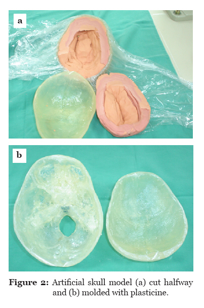
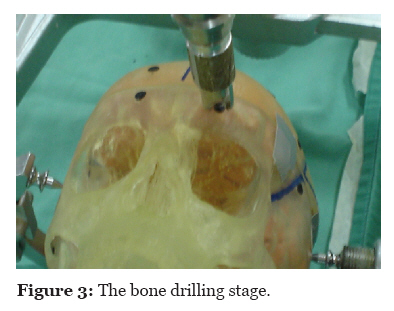
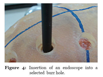
vision-guided robotic system to perform basic neurosurgical procedures. Keywords: computer-assisted surgery, endoscopes, neurosurgery, robotics, skull Introduction Robots have been used in operation theatres as of the last few decades (1). Neurosurgery is one of the major fields in which the application of robots during surgery is feasible. Robotic technology has been incorporated into stereotactic and endoscopic procedures (2,3). Other key neurosurgical applications for robots include robotised microscope (4), telepresence (5), and tumour resection (6). Technically, surgical robots can be divided into passive or active systems. A passive system is one in which the surgeon provides the physical energy to drive the surgical tool (7). An active robotic system is one in which the robot actively interacts with a patient, allowing more complicated motions to be realised. This latter system provides greater autonomy. In addition, the surgeon has the ability to supervise and intervene when necessary (8). The surgical robots can also be classified by how the surgeon interacts with them. They are divided into supervisory-controlled system, telesurgical system, and shared-control system. In a supervisory-controlled system, the robot automatically performs the task based on the downloaded surgical plan and is supervised by the surgeon. The surgical plan is programmed using either computed tomography (CT) scan or magnetic resonance brain images of a patient. The robotic telesurgical system is a system in which the surgeon controls the robot in real time via the haptic interface. The robot replicates the surgeon’s motions from the interface. In a shared-control system, the surgeon has full control of the procedure and the robot offers steady hand manipulation of the instrument (9). In this study, we examined the ability of our industrial robotic arm to perform basic neurosurgical procedures, namely bone drilling and endoscopic manoeuvres, on artificial skull models. The robotic system was fully guided by a visual system, thus making this system different from the aforementioned robotic systems. A program was created to transform visual coordinates to the robotic coordinates, thus enabling the robot to execute the tasks. The robot’s abilities were measured via the capability of the robot to recognise the target and perform the tasks. The accuracy of the robot was also assessed. Materials and methods The robot used in this study was an Adept Cobra 600 robot (Adept Technology Inc., San Jose, CA). The Adept Cobra 600 robot (Figure 1) is a selective compliant assembly robot arm (SCARA) robot with 4 joints. Joints 1, 2, and 4 provide rotational movements, and joint 3 moves in translation. Joint 1 is also referred to as the shoulder and has motion limited to approximately 105°. Joint 2, which also referred to as the elbow, has motion limited to approximately 150°. Joint 3 allows vertical translation of the quill with a maximum stroke of 210 mm. Joint 4, also referred to as the wrist, allows approximately 360° of rotational movement. A 25-mm lens charge-coupled device (CCD) camera functioned as the visual system. The camera was mounted to the robotic arm. The camera had input and output channels, and the lens could be focused manually. The images produced were in the greyscale form. Preparation of artificial skull models The artificial skull models were made using the stereolithography apparatus (SLA) system. The brain CT scan images were transferred to the workstation, and using special software, the images were translated. The skull models were constructed using acrylic resin. Subsequently, the skull model was cut into two parts using a saw. Plasticine was moulded and wrapped with thin plastic and placed into the skull (Figure 2). The purpose of this step was to create soft material in the skull that would act like a brain. This detail is important because the Midax Rex perforator uses a mechanical sensor and will only stop once it senses the soft component. Two basic surgical procedures were tested in this study: bone drilling and endoscopic manoeuvres. Bone drilling The skull model was placed into different surgical positions, simulating a real operation: supine with head in neutral position, supine with head in left or right lateral position, sitting position, and prone position. To avoid movement during the procedure, the skull models were clamped on a Mayfield three-pin clamp. The Midax Rex perforator was attached to the gripper and held tightly with screws. The tubing was fixed to the gas tank and foot pedal. A total of 4 targets were placed in supine position with the head in neutral position. There were also 10 targets at different sites in the sitting position, 5 targets at each side in lateral positions, and 6 targets placed on the skull surface in the prone position. These targets were black, rounded cardboard, each measuring 1 cm in diameter. The targets were glued to the skull surface. Only 1 target was exposed at a time for image capturing; the remaining targets were covered with surgical towel. The camera was placed at 54.5 cm from the skull surface, similar to the position where the camera was calibrated. The image of the first target was captured. Using the V+ program, a specific set of commands were created to analyse the image. Image processing involved many steps. First, in the image-capturing stage, the image was stored in pixels. Pixel is the basic unit of a vision system. The number of pixels that a system can process determines its resolution and influences the computer processing time needed to analyse the image. Subsequently, using a Gaussian filter, the image was filtered to reduce the noise and prepare the image for further processing. Later, the edge of the image was detected using a Sobel operator (edge detection). Finally, the image centroid was determined via the method of moments. Using a mathematical calculation that was set in the program, the image coordinates were transformed into robot coordinates. Next, the task was executed. The robotic arm together with the perforator moved to the target. The perforator was instructed to descend until it touched the skull surface. Using the mechanical sensor located at joint 4, the program was constructed in such a way that the perforator would stop automatically once the sensor detected a force of more than 2 pounds. At this stage, the accuracy of the robot was assessed by measuring the distance, using the computer, between the centre of the target and the point at which the perforator hit the target. The robotic arm was then instructed to return to home position. The procedure was repeated twice. The repetitive value (repeatability) was recorded. After the second attempt, the robotic arm was given a force speed at 0.5% of maximum velocity and as soon as the perforator hit the target, the pedal was pressed and the perforator was allowed to spin and drill the skull (Figure 3). The perforator continued to drill and stopped automatically when it sensed the soft part (plasticine). The robotic arm was then instructed to return to home position. These steps were repeated for all targets located at different sites and different positions. Endoscopic Manoeuvre In this section, only the burr holes that were perpendicular to the endoscope were chosen. There were 10 burr holes in total, and the centroid of the targets were determined via image processing. These coordinates were transformed into robotic coordinates and the task was executed. Upon execution, the robotic arm together with the endoscope moved to the targeted burr hole. On command, the endoscope descended and entered the burr hole to touch the target marker. The accuracy was measured. Following that, the robotic arm was instructed to ascend and move to home position. These steps were repeated twice. The repetitive values were measured. Once the accuracy and repetitive values were measured, the endoscope was instructed to return to the burr hole and descend. The endoscope was given some minimal force to penetrate the plasticine and descend on command (Figure 4). The ability of the robotic arm to recognise and insert the endoscope into the specific burr hole on command was assessed. These procedures were repeated for the rest of the selected burr holes. Results In the supine position, the accuracy was 1.0 mm for all targets. The repetitive values ranged 0.04–0.17 mm. In the sitting position, a total of 8 burr holes were successfully performed. The accuracy ranged 0.1–1.0 mm with the repetitive values ranging 0.10–0.92 mm. In the prone position, the accuracy ranged 0.5–1.0 mm with the repetitive values ranging 0.08–0.31 mm. In the left lateral position, only 2 burr holes were successfully performed. The accuracy was 1.0 mm. The repetitive values for these 2 left lateral burr holes were 0.03 and 0.11 mm, respectively. Similarly, in the right lateral position only 2 burr holes were able to be performed. The calculated accuracy was 1.0 mm and the repetitive value was 0.10 mm. The results are summarised in Table 1. For the endoscopic manoeuvre, the accuracy ranged 0.3–1.0 mm, and the repetitive values ranged 0.31–0.77 mm. Discussion In our robotic system, the ability to perform the tasks was limited by the degree of freedom (DOF). DOF referred to the number of possible movements that could be made at a joint. The movements could either be translational or rotational. For complete freedom of movement, 6 DOFs are required. If we apply this principle to the human upper limb, the elbow has 1 rotational DOF, the elbow and wrist have 3 rotational DOFs, and the palm is considered to have 7 DOFs as a result of the sum of the shoulder, elbow, and wrist. With 7 DOFs, therefore, better precision can be obtained. Four DOFs would limit the surgeon’s ability (10). One study was done comparing 4-DOF and 6-DOF robots performing some endoscopic procedures. The study revealed that the time taken and error rate to perform the procedures by 6-DOF robot were significantly less as compared with the 4-DOF robot (11). Our robot has 4 DOFs. Because of this fact, the robot could only perform some limited movements. The robotic could only make rotational motions (joints 1, 2, and 4) and vertical translational movements (joint 3). To make a burr hole using a perforator, the perforator has to be perpendicular to the surface. Therefore, with our present system, the robotic arm can only perform bone drilling if the arm is perpendicular to the skull surface (supine, prone, and some sitting positions). The wide angulation of the skull in the lateral position did not allow for the proper drilling of the bone. Similarly, with the endoscopic manoeuvre, the endoscope could only be inserted if the burr hole was perpendicular to the robotic arm. The accuracy of our system was determined by many factors. First, the visual system was represented by a CCD 25-mm lens with an 8.1 pixel camera. The image taken by the camera was kept in greyscale form. Subsequently, the image was converted to binary form. Here, the centre of the image (target) was determined via image processing based on how much of the image represented by pixels was detected. If a higher pixel and higher resolution camera had been used, the image taken would have been better and the centroid coordinates more accurate. The problem with visual system applied to both bone drilling and endoscopic manoeuvres. The other crucial factor that may affect the accuracy and repeatability was the inconsistency in the height of the camera from the skull surface. During the camera calibration, the height of the camera from the surface was fixed at 54.5 cm. Given that the skull surface was uneven and contoured, the height was different every time an image was captured. Another factor that may influence the accuracy of our robotic system, particularly at different skull positions, was the amount of illumination. As the robot was located in a large laboratory, the amount of light that fell on the target was very difficult to control. Optimum illumination is crucial because it can influence the amount of pixel that can be detected by the camera. This problem can be overcome by providing additional illumination. Safety was another issue that needed to be addressed. The traditional safety methods designed for industrial robots are not sufficient for medical robots. For instance, industrial robots are required to be kept in a locked room so that nobody can enter the room and interact with the robot. In contrast, the surgical robot required direct contact with the patient and surgeon. In addition, medical robots are used in patient care settings and have impacts on human life, whereas industrial robots deal with products produced in factories. Therefore, the safety requirements for medical robots are more stringent and critical (12–14). Due to some limitations, the safety mechanism in our robot was still lacking. In this study, we had to stop the robot manually once the perforator stopped drilling. Similarly, with the endoscopic manoeuvre there was no specific safety system attached to the robot or the endoscope, although the robot was able to follow the command based on the program. Table 1: Number of targets and completed burr holes plus the accuracy and repeatability at different positions
Conclusion Our robotic system was able to behave like a surgical robot. The accuracy of the vision guided robotic arm ranged 0.1–1.0 mm. Much refinement in the use of robotic systems for neurosurgical procedures is needed. For future work, we would like to improve the number of DOFs, thus allowing for more joint movements. A mechanism is also needed to ensure that the height of the camera from the skull surface can be maintained even when the skull is placed into different positions. More importantly, safety mechanisms need to be developed and established before work can be extended in animal models. References
© Copyright 2011 - Malaysian Journal of Medical Science The following images related to this document are available:Photo images[mj11022f4.jpg] [mj11022f3.jpg] [mj11022f1.jpg] [mj11022f2.jpg] |
| |||||||||