 |
| About Bioline | All Journals | Testimonials | Membership | News |
|
||||||
|
||||||
Braz J Oral Sci, Vol. 9, No. 4, October-December, 2010, pp. 439-442 Shear bond strength test using different loading conditions –a finite element analysis Rodivan Braz1, Mário Alexandre Coelho Sinhoreti2, Aloísio Oro Spazzin3, Sandro Cordeiro Loretto4, Arine Maria Viveros de Castro Lyra1, Agenor Dias de Meira-Júnior5 1DDS, MS, PhD,
Professor, Department of Restorative Dentistry, School of Dentistry, University
of Pernambuco, Recife, PE, Brazil Correspondence to: Aloísio Oro Spazzin Departmento de Odontologia Restauradora,Á rea Materiais Dentários, FOP/UNICAMP, Piracicaba, SP, Brazil. Av. Limeira 901, Vila Rezende, 13414-903, Piracicaba, SP, Brazil; Phone: +55 (19) 2106 5345, Fax: +55 (19) 2106 5211 E-mail: aospazzin@yahoo.com.br Received for publication: May 03, 2010 Code Number: os10051 Abstract Aim: This study evaluated the stress distribution at the bond interface during
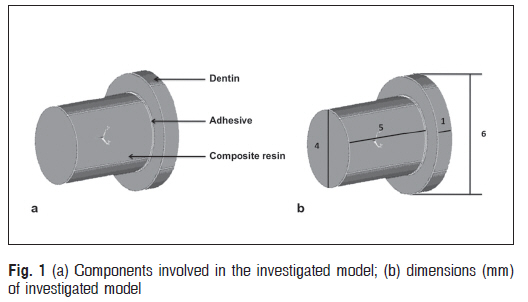
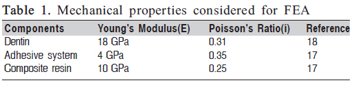
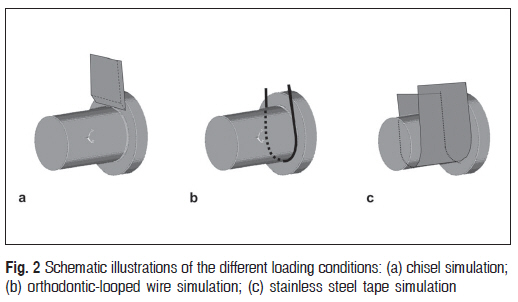
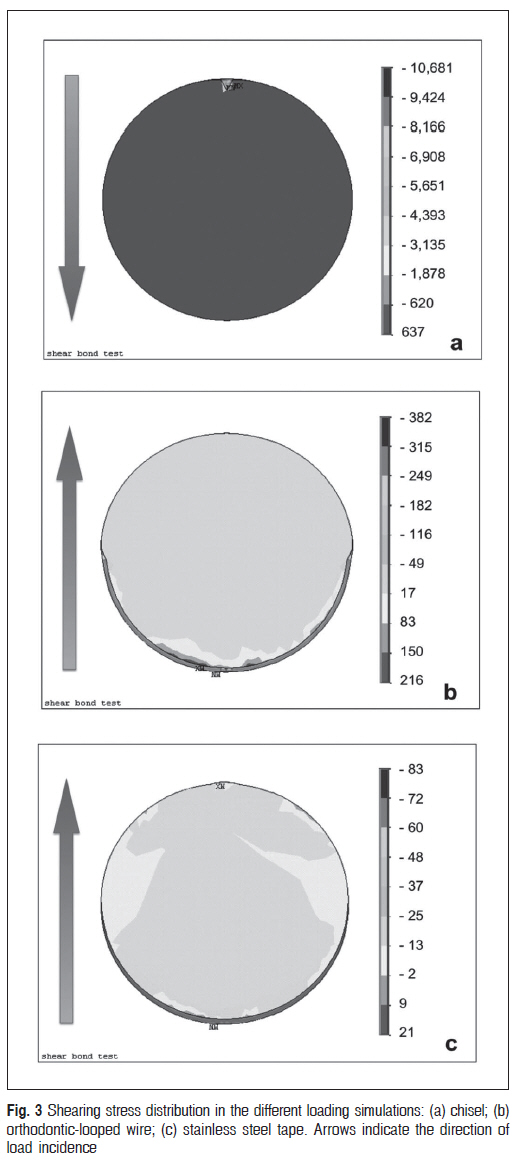
shear bond strength testing for three loading conditions. Keywords: shear bond strength, stress distribution, loading. IntroductionIn-vitro mechanical tests of dental restorative materials provide dental practitioners with guidance as regards material selection criteria and identifying patterns of optimal clinical use of material. The quality of adhesive material bonding is frequently verified by various laboratory tests, using shear and tensile efforts under certain limitations1. In 1997, a study evaluated 50 studies that used laboratory tests to quantify the bond strength at the bond interface, and observed that 80% used the shear bond strength (SBS) test in its several forms2. Today, use of the microtensile bond strength (µTBS) and microshear bond strength (µSBS)3 tests have increased considerably. However, several recent studies still use the SBS test to evaluate adhesive material bonding4-10. In some situations, sectioning of the specimen forµ TBS induces its loss due to failure before the test, and µSBS cannot be used because of the difficulty of making specimens with some materials. In these cases, the SBS test may be used to evaluate adhesive material bond strength. It is important to consider the changes in the test procedures commonly applied in different investigations that have the same aim: to determine the bond strength. For this reason, analyses of the same material inevitably produce different bond strength data1,11-14. A factor concerns the stress created at the bond interface by the load applied. Sinhoreti et al.15 compared the morphological characteristics of the fractured compositedentin interface, using an ISO specified test (loading applied with chisel), and non-specified tests (loading applied with stainless steel tape and orthodontic-looped wire). The authors found that the failures were fractures between the adhesive and the dentine when the stainless steel tape was used, suggesting that this loading condition was not subject to the complexity of stress produced by a loading test1. However, no information was found in the literature on how the stress distribution occurs at the bond interface during the SBS test under these three conditions. The simultaneous interaction of the many variables affecting a restorative system can be studied using simulation in a computerized model. The finite element analysis (FEA) consists of dividing a geometric model into a finite number of elements, each with specific physical properties. The variables of interest are approximated with some mathematical functions. Stress distributions in response to different loading conditions can be simulated with the aid of computers with dedicated software16 . The aim of this study was to compare the effects of different loading conditions (chisel, orthodontic-looped wire and stainless steel tape systems) used in shear bond tests on stress distribution at the dentin-adhesive interface using FEA. The hypothesis tested was that the loading condition simulating a stainless steel tape creates a more uniform stress distribution at the bond interface. Materials and methodsA 3-D model was created of a specimen for evaluation by the shear bond strength test, using three cylindrical volumes representing the dentin (6 mm diameter and 1 mm thick), adhesive system (4 mm diameter and 10 µm thick) and composite resin (4 mm diameter and 6 mm thick). The study model presented the configurations and dimensions presented in Figure 1. The FEA was performed with the FE software program (ANSYS rel 5.2, Ansys Inc., Houston, TX, USA). The model components were assumed to be isotropic. The elastic constants used in the calculations were obtained from the literature (Table 1)17-18. The Solid92 element was used, dentin and composite resin (the solid corpus), with 10 nodes and three degrees of freedom per node. The following assumptions were made: there is complete bonding between dentin, adhesive and composite resin; dentin was assumed to contain elastic isotropic material. The volumes were meshed, finally resulting in a 3-D FE model with 15,436 elements and 23,835 nodes. All of the nodes on the external dentin surface were constrained in all directions. A linear static structural analysis was performed to calculate the stress distribution at the dentinadhesive interface, under a total load of 200 N. This load produced a mean shearing stress of approximately 16 MPa. Three experimental models simulating different loading conditions were performed (Figure 2): -Chisel group –punctual loading at the adhesive-dentin interface, simulating the load applied on the specimen with a chisel; -Wire group – application of a radial loading 0.5 mm from adhesive-dentin interface, simulating the load applied on the specimen with orthodontic-looped wire; -Tape group – application of a radial pressure with 5 mm of width, simulating the load applied on the specimen with a stainless steel tape; Accuracy of the model was checked using convergence tests. Particular attention was given to the refinement of the mesh resulting from the convergence tests at the interfaces. The results were qualitative and quantitatively analyzed with regard to shearing stress distribution at the dentin-adhesive interface. Results The stress distribution at the bond interface for the different loading conditions is shown in Figure 3. For the Chisel Group, the bond interface presented high stress levels concentrated next to the point of load application. The shearing stress values ranged from -10681 to 637 MPa. For the Wire Group, the bond interface presented stress concentration along the radial loading axis, but it was considerably lower than that for the chisel. The shearing stress values ranged from -382 to 216 MPa. For the Tape Group, the bond interface did not present peaks of stress concentration, showing more uniform stress distribution. The shearing stress values ranged from -83 MPa to 21 MPa. DiscussionThe results of the current study showed more homogenous stress distribution at the bond interface during the shear bond strength test using stainless steel tape, supporting the hypothesis of the study. The larger area of contact between the stainless steel tape and the specimen created stress distribution over the entire bond interface. Therefore, the lower stress concentration along the bond interface explains that using tape, sliding occurs between the components of the specimens, characterizing a shear bond strength test. As regards the loading using the chisel, severe stress concentrations were presented near the loading site, caused by the simulation of the small area of contact between the chisel and the specimen (punctual load). This loading condition creates stresses of complex nature, involving cleavage, traction and compression1,19. Cohesive failures in dentin are commonly found, with portion of the substrate being literally pulled away1,20. The strength values obtained must be ignored when these cohesive failures occur in the dentin, once they do not represent the mean strength measured at the bond interface, and but the cohesive strength of the substrate19-20 . The loading simulating the orthodontic-looped wire also showed stress concentrations, although considerably lower compared with the chisel. A region showing the presence of red color near the radial load observed in Figure 3 indicates the effect of the stress concentrations due to the small area of contact between the wire and specimen. The stresses are not distributed along of whole the interface as when using tape. Sinhoreti et al.1 considered the failure using wire caused by flexional stress, promoting cohesive fracture of the composite or cohesive fracture of the adhesive. The wire has circular transversal section so the force cannot be applied joint to interface, compatible with the simulation using wire in the current study, in which the radial load was applied 0.5 mm from the bond interface. This fact could increase the flexion pattern at the bond interface21-22 . In addition, the data of the present study explained the results found by Sinhoreti et al.1. Among the three loading conditions tested, they found the lowest bond strength values for loading using tape, and interfacial failures between dentin and adhesive, suggesting that tape creates the best condition for establishing the true shear bond strength test. The bond failure occurs due the sliding between the surfaces of composite resin and dentin, as result concentration of tangential force. Moreover, this load produces no fulcrum point or flexion of the composite cylinder, or superficial cleavage, as observed for the load with orthodontic-looped wire and chisel, respectively1 . Della-Bona et al.23 suggested that the SBS test is inadequate as a means of assessing the quality of the adhesive bond of resin composite to ceramic. However, in some situations, sectioning the specimen for the µTBS induces its loss by failure before of the test. In these cases, the SBS test using the stainless steel tape may decrease the tensile and compressive stresses during the test to evaluate the bond of these friable materials. Considering the results obtained with 3-D FEA and literature available, it may be concluded the loading with stainless steel tape allows more uniform stress distribution along the bond interface. Therefore, loading using a tape is a more reliable method and must be used to evaluate the bond strength of adhesive materials concerning the aim of the SBS test. AcknowledgementsThe authors thank the Dr Cezar Augusto Garbin (in memoriam) for his generous help, essential for carrying of study. The Faculty of Mechanical Engineering of the Engineering and Architecture School, University of Passo Fundo, RS, for its help with the element finite analysis. References
Copyright 2010 - Braz J Oral Sci The following images related to this document are available:Photo images[os10051t1.jpg] [os10051f2.jpg] [os10051f3.jpg] [os10051f1.jpg] |
| |||||||||