 |
| About Bioline | All Journals | Testimonials | Membership | News |
|
||||||
|
||||||
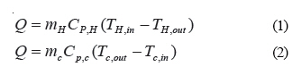
Iranian Journal of Environmental Health Science & Engineering,Vol. 3, No. 4, 2006, pp. 273-284 APPLYING THE HEAT INTEGRATION IN ORDER TO ENVIRONMENTAL POLLUTANTS MINIMIZATION IN DISTILLATION COLUMNS *1A. H. Javid, 2A. Emamzadeh, 3A. A. Hamidi, 1A. Arjmandzadeh 1Graduate School of Environment and Energy, The Science and Research Campus, Islamic Azad University *Corresponding author-Email: ahjavid@gmail.com Tel: +98 21 4480 4160, Fax: +98 21 4480 4165 Received 1 July 2006; revised 10 August 2006; accepted 26 September 2006 Code Number: se06038 ABSTRACT Due to the close relationship between the energy and environmental problems, recovering technology and optimizing energy consumption have a major role in environment protection by minimization the atmospheric pollutants such as SOX, COX, NOX. This minimization may decrease the greenhouse effect, and the ozone layer destruction. On the other hand, optimization of Energy consumption and its recovering may minimize the water and hot oil consumption at the heat exchangers (reboilers and condensers) in petroleum distillation columns, specially. The present research has been performed about the kerosene pre-fractionation unit of one of the country's oil refineries. This system includes two distillation columns with a simple arrangement. Considering that the distillation section consumes a great deal of energy in the chemical and petroleum industries, hence studying the ways in which we may decrease this consumption is of great importance. One of these retrofit solutions is the heat integration, which is going to be presented in this research with a different idea from the other previous methods. This method makes it possible to add a shell and tube heat exchanger for performing a part of condensation and evaporation operation which can decrease the heat duties of reboilers and one of the condensers. To this end , the distillation columns were studied in the process and then the proposed model of columns arrangement were simulated by heat integration with all input and output streams using the Aspen Plus software, version 11.1 and the Rad Frac model in this software. The result has showed itself as a save of 14.26%, 10.86% and 14.26% in energy, water and hot oil consumption, respectively. On the other handthis system will decrease emission of SO2 and CO2 to atmosphere, 28 kg/h and 837 kg/h, respectively. Key words: Heat integration, distillation columns, refinery, water, energy INTRODUCTION Pinch technology indicates the possibility of heat recovery in the process in a way that, through this method, heat exchange of hot streams that should become cold and cold streams that should become hot are possible. The pinch design method and heat integration technology developed earlier followed several rules and guidelines to allow design for minimum utility (or maximum energy recovery) in the minimum number of units. Occasionally, it appears not to be possible to create the appropriate matches because one or other of the design criteria cannot be satisfied. Heat integration is more than just pinch technology and heat exchanger networks. Today, it has for wider scope and touches every area of process design (Smith, 2005). The dominant heating and cooling duties associated with a distillation column are the reboiler and condenser duties. In general, how ever, There will be other duties associated with heating and cooling of feed and product streams. These sensible heat duties usually will be small in comparison with the latent heat changes in reboilers and condensers. There are two possible ways in which the column can be heat integrated with the rest of the process. The reboilers and condensers can be integrated either across, or not across the heat recovery pinch (Linnhoff, et al., 1983; Umeda, et al.,1979). If both the reboiler and condenser are integrated with the process, this can make the column difficult to start up and control. However, when the integration is considered more closely, it becomes clear that both the reboiler and condenser do not need to be integrated. Above the pinch the reboiler can be serviced directly from the hot utility with the condenser integrated above the pinch. Below the pinch, the condenser can be serviced directly by cold utility with the reboiler integrated below the pinch. The reboiler and condensers duties are on opposite sides of the heat recovery pinch and the column does not fit (Umeda et al.,1979). Although the reboiler and condenser duties are both above the pinch the heat duties prevent a fit part of the duties can be accommodated, and if heat integrated that would be a saving, but less than the full reboiler and condenser duties. If an inappropriately placed distillation column is shifted above the heat recovery pinch by changing its pressure, The condensing stream, which is a hot stream is shifted from below to above the pinch. The reboiling stream which is a cold stream, stays above the Pinch if the inappropriately placed distillation column is shifted below the pinch. Then the reboiling stream, which is a cold stream is shifted from above to below the pinch. The condensing stream stays below the pinch, thus appropriate placement is a particular case of shifting streams across the pinch. If a distillation column is inappropriately placed across, the pinch, it may be possible to change its pressure to achieve appropriate placement (Smith and Linnhoff, 1998). If the distillation column will not fit either above or below the pinch , then other design options can be considered one possibility is double-effect distillation (Smith and Linnhoff,1988). Another design options that can be considered if a column will not fit is the use of an intermediate condenser, because the intermediate condenser changes the heat flow through the column with some of the heat being rejected at a higher temperature in the intermediate condenser. For intermediate reboilers, part of the reboiler heat is supplied at an intermediate point in the column at a temperature lower than the reboiler temperature (Dhole and Linnhoff, 1993; Flower and Jackson,1964; Kayihan 1980). In order to avoid the uncontrolled energy consumption, and to protect the national energy resources, the energy recovery by the new methods and scientific manners should be considered. In fact performance of energy recovery projects and optimizing consumption methods, prevent energy losses and will also save the environmental resources. Overall strategy for chemical and petroleum processes design and heat integration can describe these processes that should be designed as part of a sustainable industrial activity that retains the capacity of ecosystems to support both industrial activity and life into the future. Sustainable industrial activity must meet the needs of the present without compromising the needs of future generations. For chemical and petroleum processes design, this means that processes should use raw materials as efficiently as is economic and practicable, both to prevent the production of waste that can be environmentally harmful and to preserve the reserves of raw materials as much as possible. Processes should use as little energy as economic and practicable, both to prevent the buildup of carbon dioxide and other pollutants in the atmosphere from burning fossil fuels and to preserve reserves of fossil fuels. Water must also be consumed is sustainable quantities that do not cause deterioration in the quality of the water source and the long-term quantity of reserves. Aqueous and atmospheric emissions must not be environmentally harmful, and solid waste to landfill must be avoided. The major emissions from the combustion of fuel are CO2, SOx, NOx and particulates. The products of combustion are best minimized by making the process efficient in its use of energy through efficient heat recovery and avoiding unnecessary thermal oxidation of waste through minimization of process waste. Flue gas emissions can be minimized at source by increased energy efficiency at the point of use (better heat integration) (Smith, 2005). In the chemical and petroleum processes, there are cold and hot streams beside the distillation columns which makes it possible to heat exchanging between these streams. Therefore this research aims at finding a way to heat exchanging between these streams in order to optimize energy consumption, decrease in cooling water and hot oil consumption and minimize environmental pollutants. One of these retrofit solutions is heat integration. When distillation columns are heat integrated, energy consumption will be decreased to almost a great extent and it has been showed that there is a considerable difference between integrated and non-integrated distillation columns regarding to energy consumption. By considering this fact that fractions of petroleum components may release in heat process; according to their boiling point, Aspen Plus software demonstrates each stream fractions as Pseudo Component (PC) which refers to the criteria of American Society of Testing and Materials (ASTM). The process which is the kerosene pre-fractionation unit of a refinery consists of two simple continuous distillation columns, i.e. at first the light product is separating by the first column and the middle and heavy products are separated by the second column. In this research the feed to the first column is first converted to the top-light product (Light) and its bottom-heavy product (Stream). The bottom-heavy product enters into the second column, where is converted to light product at the top (Heart) and the heavy product at the bottom (Heavy). The existing heat exchangers besides the distillation columns consist of condensers (shell and tube heat exchangers which perform the condensation operation) and reboilers (shell and tube heat exchangers which perform the evaporation operation). The first column has 53 trays and the second column has 65 trays. In the first column the feed enters to the tray no.30 and the bottom product of this column feeds to the tray no.30 of the second column. MATERIALS AND METHODS According to the last statements, this study carried out using Aspen Plus. The main formula and correlations which is used by this software for this project are as follow:
Where: Q= Heat transferred per unit time (J/s=w) mH ,mc= Mass flow rates of the hot and cold stream (kg mol) CP,H,CP,c = Specific heat capacity of the hot and cold streams (J/ (kg mol) (k)) TH,in, TH,out = Hot stream inlet and outlet temperature (k) TC,in, TC,out = Cold stream inlet and outlet temperature (k)
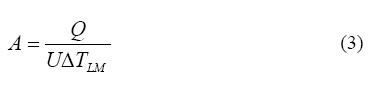
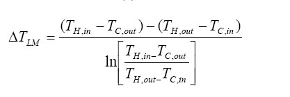
Where: A= Heat transfer area (m2) Q= Heat transferred per unit time (J/s=w) U= Overall heat transfer coefficient (J/s.m2.k) Δ TLM=Logarithmic mean temperature difference (k)
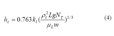
For condensation in side horizontal tubes:
Where: hc = Condensing film coefficient (w/m2.k) kl = Thermal conductivity of the liquid (w/m.k) ρL = Density of the liquid (kg/m3) g = Gravitational constant (9.81 m/s2) μl = Viscosity of the liquid (N.S/m2 or kg/m.s) L= Tube length (m) m= Flow rate of condensate (kg/s) NT = Number of tubes A simple correlation for nucleate boiling that can be used for the preliminary design of Kettle and horizontal Thermosyphon reboilers.
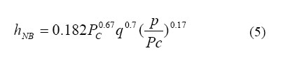
Where: hNB=Nucleate boiling coefficient (w/m2.k) Pc= Liquid critical pressure (bar) P= Operating pressure (bar) q= Heat flux (w/m2) = hNB (Tw-TSAT) Tw= Wall temperature of the heating surface TSAT= Saturation temperature of the boiling liquid
Shell-side film Coefficient in shell and tube heat exchangers:
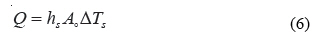
Where: Q= Heat transferred per unit time (J/S=W) hs=Film heat transfer coefficient on the out side (shell-side) of the tubes (w/m2.k) Ao= Heat transfer area outside (shell-side) of the tubes Δ Ts = Temperature difference across the outside (shell-side) film (k)
Tube-side film coefficient in shell and tube heat exchangers: Q = hT AI ΔTT (7) Where: Q= Heat transferred per unit time (J/S=W) hT = Inside (tube-side) film heat transfer coefficient (w/m2.k) AI = Inside (tube-side) heat transfer area of tubes (m2) ΔTT = Temperature difference across the inside (tube-side) film (k)
For a simple distillation column which has one feed, two products, one reboiler and one condenser, overall material balance can be written as: F=D+B (8) Where: F= Feed stream flow rate into the column ((kmol)/(s)) D= Output product flow rate from top of the column ((kmol)/(s)) B= Output product flow rate from bottom of the column ((kmol)/(s))
Material balance around the condenser can be written as: V=L+D (9) Where: V= Input vapor flow rate to the condenser ((kmol)/(s)) L=A part of the output liquid flow rate from the condenser which is reflux stream flow rate to top of the column ((kmol)/(s)) D=An other part of the output liquid flow rate from the condenser which is output product flow rate from top of the column ((kmol)/(s)) Material balance around the reboiler can be written as: L' = V' + B (10) Where: L'= Output liquid flow rate from bottom of the column ((kmol)/(s)) V' = Output vapor flow rate from the reboiler which is input vapor flow rate to bottom of the column ((kmol)/(s)) B = Output product flow rate from bottom of the column ((kmol)/(s))
An overall energy balance can be written as:
FHF +Qreb= DHD + BHB+Qcon (11) Where: F = Feed stream flow rate into the column ((kmol)/(s)) D= Output product flow rate from top of the column ((kmol)/(s)) B= Output product flow rate from bottom of the column ((kmol)/(s)) HF = Feed stream enthalpy into the column (J/(kmol)) HD = Output product enthalpy from top of the column (J/(kmol)) HB = Output product enthalpy from bottom of the column (J/(kmol)) Qreb=Reboiler heat duty (W) Qcon=Condenser heat duty (W)
Energy balance around the condenser can be written as: VHV = LHL + DHD + Qcon (12) Where: V= Input vapor flow rate to the condenser ((kmol)/(s)) L= A part of the output liquid flow rate from the condenser which is reflux stream flow rate to top of the column ((kmol)/(s)) D= An other part of the output liquid flow rate from the condenser which is output product flow rate from top of the column ((kmol)/(s)) HV = Input vapor enthalpy to the condenser (J/(kmol)) HL=A part of the output liquid enthalpy from the condenser which is reflux stream enthalpy to top of the column (J/(kmol)) HD =Another part of the output liquid enthalpy from the condenser which is output product enthalpy from top of the column (J/(kmol)) Qcon = Condenser heat duty (W)
Energy balance around the reboiler can be written as: V'HV' + BHB = L'HL' + Qreb (13) Where: L'= Output liquid flow rate from bottom of the column((kmol)/(s)) V'= Output vapor flow rate from the reboiler which is input vapor flow rate to bottom of the column ((kmol)/(s)) B = Output product flow rate from bottom of the column ((kmol)/(s)) HV= Output vapor enthalpy from the reboiler which is input vapor enthalpy to bottom of the column (J/(kmol)) HB = Output product enthalpy from bottom of the column (J/(kmol)) HL= Output liquid enthalpy from bottom of the column (J/(kmol)) Qreb = Reboiler heat duty (W)
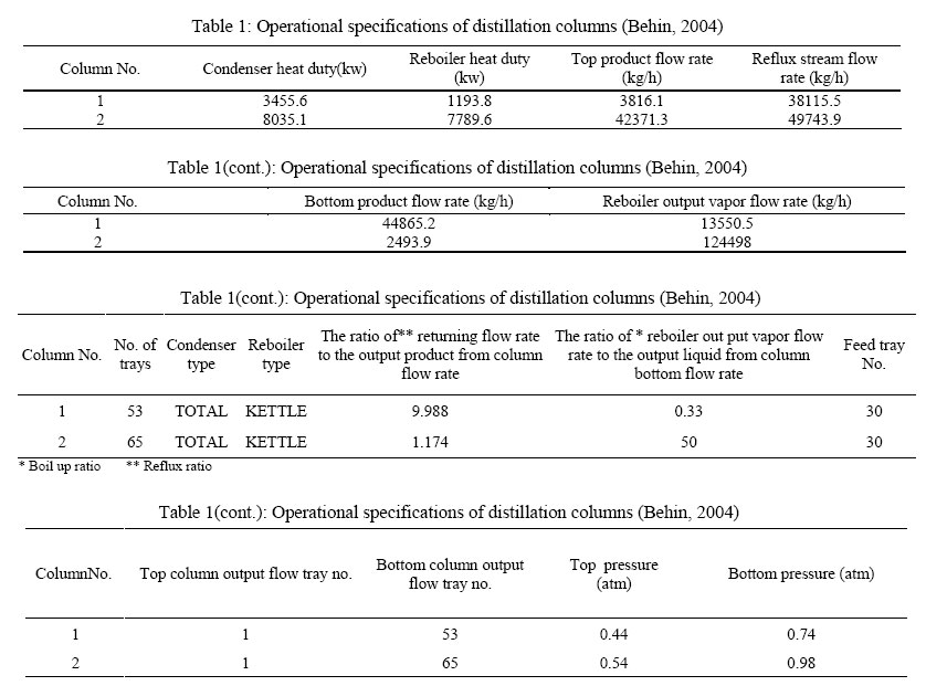
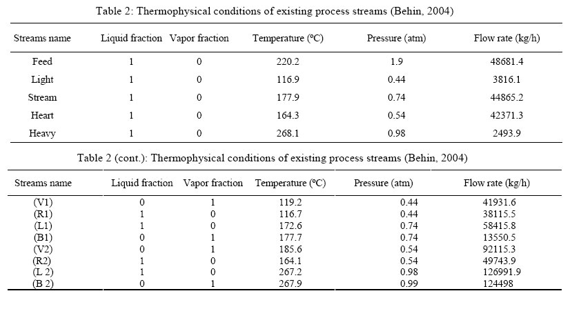
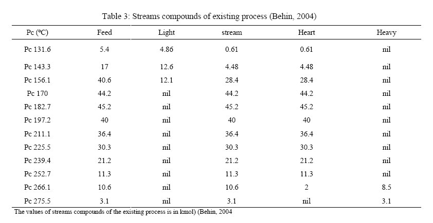
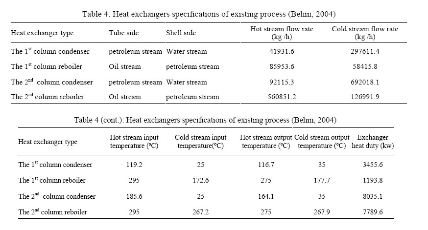
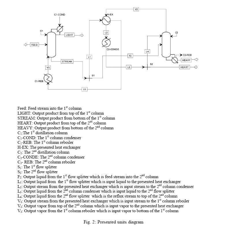
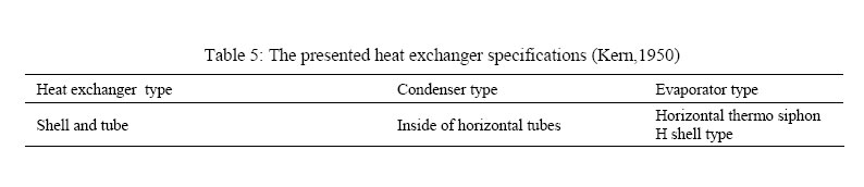
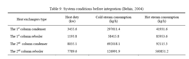
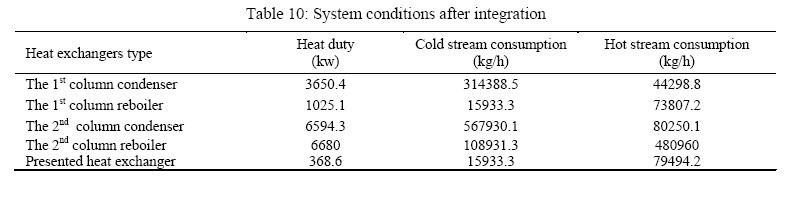
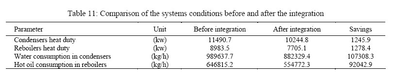
For optimization of energy consumption in the studied distillation process and for existing process heat recovering, the existing conditions should be modeled by the process modeling soft wares. It is possible to run all scenarios for carrying out these mentioned aims; after calibration of model. In Fig. 1 the diagram of the existing distillation columns has been illustrated. In order to achieve this goal Aspen Plus software which is designed specially for the petroleum and chemical processes is used. Operational specifications of the distillation columns are shown in Table 1. Table 2 shows the thermophysical conditions of the existing process streams. In Table 3 the components' mole flow has been presented. In Table 4 the heat exchangers' specifications at current situation can be observed (Behin, 2004). In the most distillation columns, the input high temperature vapor stream made by the reboiler, and the output vapor stream will be change to low temperature liquid stream by the condenser. A part of this condensate vapor returns to column as Reflux stream and another part will be used as distilled product. The reboilers convert a part of the output liquid stream from bottom of the column to vapor. The main aim of this research is investigation on possibility of using thermal energy of output vapors for optimization of energy consumption in distillation columns. Now, considering the mentioned idea and the system condition, two schemes are to be considered as follows: 1-Enter the output vapor from top of the 1st column and the output liquid from bottom of the 2nd column to a heat exchanger. 2-Enter the output vapor from top of the 2nd column and the output liquid from bottom of the 1st column to a heat exchanger. But after the modeling of the process streams, we find that the output vapor from top of the 1st column does not bear the ability to boil a part of output liquid from bottom of the 2nd column, in the first scenario. But according to this modeling, the output vapor from top of the 2nd column has the necessary heat duty to boil a part of output liquid from the 1st column, in the second scenario. Then it is possible to design a shell and tube heat exchanger for this end. Hence, by using a flow splitter (S1), a part of the output liquid stream from bottom of the 1st column (L1) is entered into a shell and tube heat exchanger and another partwill be sent as the feed (F2) to the 2nd column. The output vapor stream from top of the 2nd column (V2) will be sent to the mentioned heat exchanger. The heated output liquid stream (V1) will be sent to the 1st column reboiler and the cooled output stream (L2) is entered to the 2nd column condenser. The output liquid from this condenser (L3) will be separated to two streams using a flow splitter (S2). One of these streams will be sent to the second column as reflux stream (L4) and another part as output product is named HEART. This process is shown in Fig. 2. A summary of the presented heat exchanger design in integrated system can be observed in Table 5. RESULTS As it has been mentioned, the presented design is acceptable in which the output vapor from top of the 2nd column can boil a part of output liquid from bottom of the 1st column using a heat exchanger. The type of presented heat exchanger is shell and tube, which its evaporator is of horizontal thermo siphon type with the H shell type. The type of this units condenser is inside of horizontal tubes. Because of the purity of the resulting products from the distillation process is very important, hence, the products of integrated process must be as same as non-integrated process which is exists. The 1st splitter (S1) sends the output liquid from the bottom of the 1st column with a ratio of 0.737 as the input feed to the 2nd column, and sends the liquid stream which should be heated by the presented heat exchanger with a ratio of 0.263 into this heat exchanger. The 2nd splitter (S2) divides the cold output liquid from the 2nd column condenser with a ratio of 0.535 to reach the output product from top of the 2nd column (Heart) and with a ratio of 0.465 for the returning stream (Reflux) to the 2nd column. In Tables 9 and 10 the related conditions of the heat exchangers have been presented for the before and after integration states, respectively. DISCUSSION By comparing data of Tables 9 and 10 it can be concluded that the application of the heat integration will cause a considerable decrease in the energy consumption and hot oil and cooling water demands. On the basis of the presented data at Table 11 the savings of the energy consumption, cooling water and hot oil have been 14.26%, 10.86%, and 14.26%, respectively. By considering fuel oil as the Energy source of process, according to the specific heat value of this fuel, which is equal to 1013.06 (Kw/L), there will be a save in consumption of this fuel to the extent of 318 (L/h), approximately. On the other hand, using this amount of fuel oil can release a sum of 28 (kg/h) of SO2 and 837 (kg/h) of CO2 to the atmosphere, if the efficiency of 40% in the furnaces. Besides, the decrease of 107526.2 (L/h) of water consumption would cause the protection of the water resources. On the other hand, because of the need for high quality of water and using the water treatment systems with efficiency about 60%, it would cause a decrease in the waste water production to the extent of 178.85 (m3/h). As its produced effluent containing high concentration of Total Dissolved Solids (approx. 12000 mg/L), it is obvious that its discharging to the environment will have unavoidable side effects on the ecosystems. REFERENCES
© 2006 Tehran University of Medical Sciences Publications The following images related to this document are available:Photo images[se06038t9.jpg] [se06038t7.jpg] [se06038t4.jpg] [se06038t3.jpg] [se06038f1.jpg] [se06038t2.jpg] [se06038f2.jpg] [se06038t10.jpg] [se06038t1.jpg] [se06038t5.jpg] [se06038t8.jpg] [se06038t11.jpg] [se06038t6.jpg] |
| |||||||||
