 |
| About Bioline | All Journals | Testimonials | Membership | News |
|
||||||
|
||||||
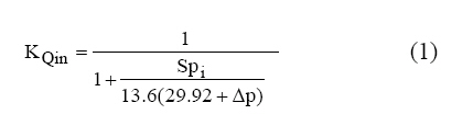
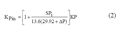
Iranian Journal of Environmental Health Science & Engineering,Vol.4, No. 4, 2007, pp. 235-242 A NEW EXHAUST VENTILATION SYSTEM DESIGN SOFTWARE* H. Asilian Mahabady, M. Omidvar, A. Rezaee, A. Khavanin, S. B. Mortazavi Department of occupational and Environmental Health, Medical faculty, Tarbiat Modares University, Tehran, Iran Received 14 August 2007; revised 2 September 2007; accepted 23 September 2007 Code Number: se07036 ABSTRACTA Microsoft Windows based ventilation software package is developed to reduce time-consuming and boring procedure of exhaust ventilation system design. This program Assure accurate and reliable air pollution control related calculations. Herein, package is tentatively named Exhaust Ventilation Design Software which is developed in VB6 programming environment. Most important features of Exhaust Ventilation Design Software that are ignored in formerly developed packages are Collector design and fan dimension data calculations. Automatic system balance is another feature of this package. Exhaust Ventilation Design Software algorithm for design is based on two methods: Balance by design (Static pressure balance) and design by Blast gate. The most important section of software is a spreadsheet that is designed based on American Conference of Governmental Industrial Hygienists calculation sheets. Exhaust Ventilation Design Software is developed so that engineers familiar with American Conference of Governmental Industrial Hygienists datasheet can easily employ it for ventilation systems design. Other sections include Collector design section (settling chamber, cyclone, and packed tower), fan geometry and dimension data section, a unit converter section (that helps engineers to deal with units), a hood design section and a Persian HTML help. Psychometric correction is also considered in Exhaust Ventilation Design Software. In Exhaust Ventilation Design Software design process, efforts are focused on improving GUI (graphical user interface) and use of programming standards in software design. Reliability of software has been evaluated and results show acceptable accuracy. Key words: Industrial ventilation, Balance method, gate method, software, VB6 INTRODUCTIONBy industries development, the amount of air contaminants that are released in workplace has grown increasingly. To reduce these contaminants, there are several methods that, one of which is control at source. Industrial ventilation is perhaps the most powerful tool available for environmental professionals to control workplace pollution. Exhaust ventilation can capture contaminants at source, refine and eliminate them, and as a result reduces workplace pollution and work related diseases caused by them (ACGIH, 2001; Burton, 1994). It is estimated that tens thousand of new industrial exhaust ventilation systems are installed annually. If we assume that the average capacity is 1000cfm with installation costs of 5$ per cfm and yearly expense of 2$ per cfm, it is apparent that this presents a considerable investment. However, many of these systems are improperly designed, are not installed according to plans, leading to tremendous loss as a result of inefficiency. All ventilation systems must be designed so perform adequately for all conditions. (William et al., 2004). If designer is not very experienced in system balance or is not familiar with air flow behavior in ducts, branch entrances, and fittings, an error in loss coefficient selection and manual calculations may cause system to be unbalanced and as a result be inefficient. As computers are getting faster, powerful, more reliable, cheaper and more accessible, their areas of application are also becoming widespread. According to above mentioned advantages, software developing in exhaust ventilation field seems to be necessary. Although Manual Design of exhaust ventilation systems is useful for occasional design (often a single branch system), the manual calculation method is time consuming and increase probability of errors. Since the mid 1970s a number of computer programs for the design of systems have been introduced in the open literature and by engineering consultants and manufactures. One type of design program has been developed for the programmable hand calculators(Barritt,1978; Malchaire, 1981; shotwell, 1984). These have the merit of explicitly and are easily use in the field but may not have advanced features, such as automatic balancing. More recently, Spreadsheet program for personal computers have been applied to ventilation design using the velocity pressure method (Rennix, 1987; Koshland and Yost, 1987; Temple systems 1999). Although these programs are powerful tools for design, but they haven’t ability to design collector and hood and may not be able to take in to account psychometric correction in design process. This study presents Exhaust Ventilation Design Software (EVDS) as a computer-aided exhaust ventilation design software for fundamental understanding of the principles underlying the system design. The software has been planned to facilitate complete exhaust ventilation system design. EVDS uses velocity pressure method for exhaust ventilation system design (ACGIH, 2001). This method has been in widespread use for about 50 years; its popularity results from the ease of initial calculation and ability to redesign system elements when necessary. Previously an alternative design procedure called equivalent foot method was published that fell further from favor in the interim, and is no longer presented in the ventilation publications (William et al., 2004). Since EVDS employs a datasheet similar to ACGIH velocity pressure calculation sheet, every designer can easily employ it. Psychometric corrections have been also considered in EVDS calculations (ASHRAE, 2001)). Altitude and temperature deviations from standard condition are automatically calculated as flow rate (KQ) and velocity pressure (KP) coefficients, taking into account psychometric correction. Intelligent structure of software makes aware user from errors accrued in design step. These warnings include high pressure difference between branches, deviation from minimum transport velocity in duct, incorrect data entering in datasheet, selection of balance method (automatically or user selection), etc. Datasheet includes 41 rows that some of them are filled by the user, and others are automatically filled by the program, based on data which is entered by the user. MATERIALS AND METHODSTo develop new software, some steps must be considered, including possibility, sketching, compiling, debugging and providing installation program (Stroo, 2001). In EVDS Design, pseudo codes were prepared at first, and then variables and algorithms were defined. Structure of algorithm for system design in EVDS was defined in Fig. 1. After the algorithm definition step, software GUI was designed. In GUI design, it has been tried to user interface be based on programming standards and also be user-friendly. For this reason we have used dropdown menus and, and designed a toolbar for fast access to necessary options. EVDS is developed in VB6 Programming environment. In EVDS design ActiveX and dll components have been used to accelerate programming procedure and fascinate programming user interface. Program debugging was performed in several steps to remove logical and syntax errors. P.C. specifications for EVDS design summarizedas below: Windows edition: Microsoft Windows XP(professional) System: AMD Athlon (tm) 64 processor 3200+3 GHZ, 512MB of RAM After program debugging, codes were compiled to a native code and optimized for fast coding. Finally, all related files compiled to a setup program in order to distribute the program and its components to end user P.C. System requirements for EVDS including: Operating system: Windows 95/98/NT4/2000/ME/XP Processor: 486DX/66 MHz PC or higher Space usage: 15MB of free Space on hard disk Software GUI EVDS has several sections which are explained as follows: Industrial ventilation system design main page: This is the main section of the program that user employ it to initialize a new project. Main sheet consists of a dropdown menu and a toolbar for fast access to other sections. In this section user can see triple pressures in a chart. In design process of EVDS psychometric corrections and static pressure effect in fan inlet also has been considered (Fig. 2). Flow (KQin) and pressure (KPin) coefficients in fan inlet can be calculated as below (ACGIH, 2001):
Where in Equation (1): SPi: Static pressure at fan inlet (in. WG) And:
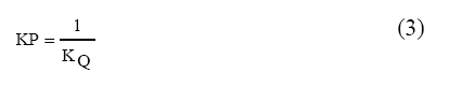
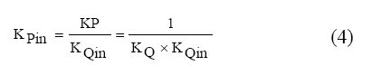
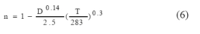
Where: KP: Pressure coefficient for psychometric correction Fan Static Pressure can also calculated as below: FSP = SPOut − SPin − VPin + Z Where: FSP: Fan Static Pressure (in. WG) Cyclone design section This section is used for cyclone design with several standard configurations. The efficiency and pressure drop in cyclone design is calculated as below (Wane T.D., 2000): η=1 −exp( −2(Cψ)1/(2n+2) (5) where:
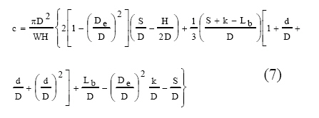
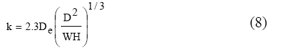
In which: T: temperature (ÚK) D: cyclone diameter (in.) And:D
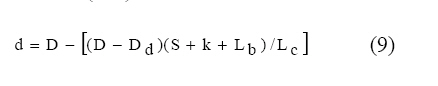
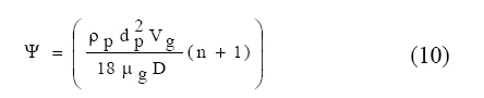
where: D: cyclone diameter (ft) and:
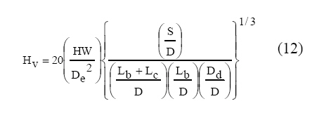
where: ρ p: Particle density (lb/ft3) Pressure loss in cyclones can be calculated as below: ΔP =1/ 2ρgV2gHv (11) where: ΔP: pressure drop in cyclone (Pa) And H v calculated as below (Dirgo, (1988); Ramachandran et al., 1991):S\
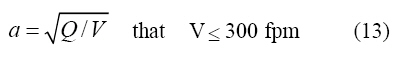
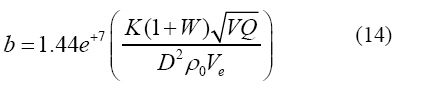
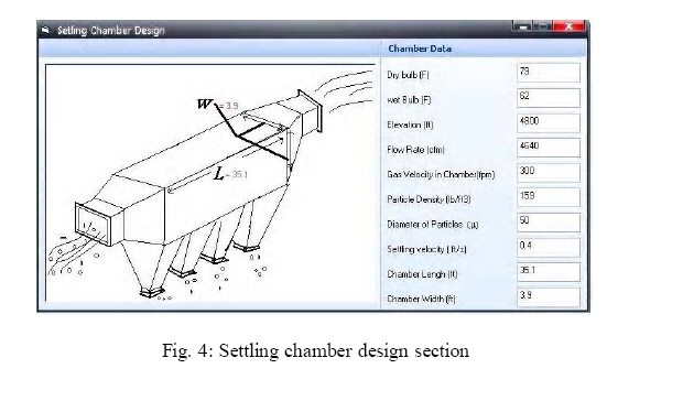
In Cyclone design section eight dimensions of cyclone can be determined; also efficiency and pressure drop can be calculated (Fig. 3). Settling chamber design Although the cost and size of chambers would make it impractical but they are most commonly utilized as precleaners for other collection equipment where there are some large size particles (over 50μm in diameter) (William, 1997). This section like cyclone design section has been designed for settling chamber dimension’s calculating (Fig. 4). User can calculate width and length of chamber as below:
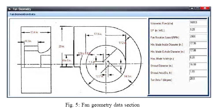
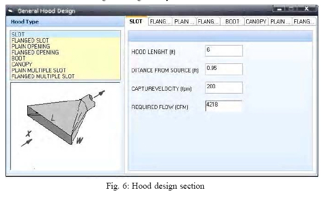
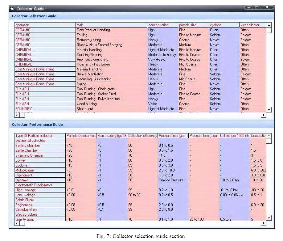
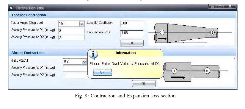
Where in Equations (13) and (15): a : chamber width (ft) D: minimum diameter of particles that remove by chamber (μ) Fan geometry section After project design, user can utilize this section to calculate impeller diameter, impeller width, and casing dimensions (Ralph, 2001).At this stage user can obtain 9 fan dimensions (Fig. 5). Hood design section If user wants to calculate flow rate, hood dimension, or see standard ventilation designs, this section can help him/her to design hood. This section has been designed based on Ventilation standards manual which helps user to design miscellaneous hood configurations including slot, flanged slot, plain opening, flanged opening, booth, canopy and plain multiple slot opening hoods (Fig. 6). Collector selection guide This section presents useful information about most collectors that are widely used in industrial ventilation system design. This information includes max loading, collection efficiency, pressure loss, and energy consumption of collector (Fig. 7). Contraction and Expansion loss This section has been designed to present contraction and expansion coefficient losses in ducts. User can also calculate losses due to contractions and expansions, in this section (Fig. 8). RESULTSAfter EVDS design and compiling, validity of software was examined by the following methods: First, output of software was compared with manually calculated results. Then software results were compared with output of projects that have been published by authorized organizations in industrial ventilation field. Also, calculations were performed in an excel worksheet and results compared with EVDS output. Software outputs show maximum error of 0.5% in boundary conditions. DISCUSSIONWith regard to EVDSvalidity examination, it seems that some errors occurred in EVDS calculations, are resulted from round-off error. Numbers are rounded off to four digits in EVDS calculations. In spite of this round off error, EVDS provides an acceptable accuracy for ventilation system design. It has a user friendly environment and can be used as comprehensive exhaust ventilation software that facilitates design process and prepare whatever a user requires for design. EVDS can design new exhaust ventilation system, check and redesign previously improperly installed systems. Another application is collector design for contaminant elimination. For future software development, it is suggested that a 3D drawing environment such as AutoCAD can be added to the software. ACKNOWLEDGEMENTSAuthors thanks to the authorities of Tarbiat Modares University (TMU) for providing facilities and is highly indebted to the Dr. jafari , associated professor of Shahid Beheshty University of Medical Science, Department of Occupational Health. REFERENCES
© 2007 Tehran University of Medical Sciences Publications The following images related to this document are available:Photo images[se07036f4.jpg] [se07036f7.jpg] [se07036f1.jpg] [se07036f3.jpg] [se07036f5.jpg] [se07036f2.jpg] [se07036f6.jpg] [se07036f8.jpg] |
| |||||||||
