 |
| About Bioline | All Journals | Testimonials | Membership | News |
|
||||||
|
||||||
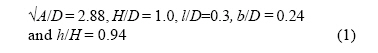
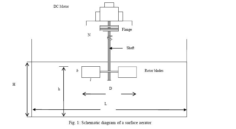
International Journal of Enviornmental Science and Technology, Vol. 3, No. 4, Autumn 2006, pp.425-433 Rectangular tank surface aerators: scale up criteria and energy conservation *A. R. Rao and B. Kumar Department of Civil Engineering, Indian Institute of Science, Bangalore, India Received 3 May 2006 Code Number: st06052 ABSTRACT: Surface aeration experiments were conducted in two types of rectangular tanks of aspect ratios i.e., length to width ratio (L/W) of 1.5 and 2 and developed simulation equations to correlate the oxygen transfer coefficient, k and power number, P0 with a parameter governing theoretical power per unit volume X. The parameter X is defined as equal to F4/3R1/3, where F and R are impellers’ Froude and Reynolds numbers respectively). Results have shown that the P0 can not be simulated singularly with either Reynolds number, R or Froude number, F, which results in scaleeffects; there appears to be a need to incorporate the effects of both F and R. It was found that P0 is uniquely related to X for rectangular aeration tanks of both aspect ratios, however, such relationships are different depending upon the aspect ratios. It has been demonstrated that energy can be saved substantially if the aeration tanks are run at relatively higher input powers. It is also demonstrated that smaller sized tanks are more energy conservative and economical when compared to big sized tanks, while aerating the same volume of water, and at the same time by maintaining a constant input power in all the tanks irrespective of their size. Key words: Froude number, oxygen transfer coefficient, power number, power per unit volume, Reynolds number, surface aerators, water and wastewater treatment INTRODUCTION Aerobic wastewater treatment uses microorganism to feed on waste in the water and convert them to sludge, carbon dioxide and water. To keep the process going, the wastewater needs to be aerated with oxygen. The two basic and widely used methods of aerating wastewater are: (1) to introduce air or pure oxygen into the wastewater body with diffusers generally called as bubble or diffused aerators and (2) to agitate the wastewater mechanically so as to promote the mass transfer of air from the atmosphere into the wastewater body, which is generally achieved by surface aerators. Surface aerators are a popular choice of aeration system because of their inherent simplicity and their competitive rate of oxygen transfer per unit of power input under actual aeration conditions. To design surface aerators in geometrically similar systems, one may require scale-up criteria for two basic parametersoxygen transfer rates and input power. Power consumption in surface aerators is generally interpreted as the Power number. Most scale-up studies in the past for mixing rely solely upon the relationship between power number and Reynolds number. While this is probably adequate for the baffled system, unbaffled system need incorporation of Froude number in the correlation for power number (Rushton, 1952). It is advantageous to use unbaffled surface aerators, because they give rise to higher fluid-particle mass transfer rates for a given power consumption (Grisafi, et al., 1994; Rao and Jyothish, 1997), which is the paramount importance in designing aeration system. In the unbaffled tanks, existence of central vortex plays an important role in enhancing the mass transfer process (Johnson and Huang, 1956; Hsieh 1991). In the literature, innumerable references are available on unbaffled cylindrical and square tanks and apparently there is no information available dealing the issues of the basic design variables of rectangular tank surface aerators. The focus of this paper is to develop the scaleup criteria for oxygen transfer and power requirement (power number) in geometrically similar rectangular tank surface aerators and from there analyze the results with an objective of conserving energy while using the different sized aerators. The experiment explained in the present paper has been conducted at the Department of Civil Engineering, Indian Institute of Science, Bangalore in India during 2003-2005. MATERIALS AND METHODS Experiments were conducted in rectangular surface aerators of aspect ratios L/W=1.5 and 2. A typical surface aerator is shown in Fig. 1. The various geometric dimensions of the aerator are: A (cross-sectional area), H (water depth), h (distance between the horizontal bottom of the tank and the top of the blades) and D (diameter of the rotor). The rotor is fitted with six flat blades in symmetrical and evenly manner such that b and l are their linear dimensions. Rotor shaft is connected to a DC motor to rotate the rotor at desired speeds. The cross-sectional areas of tanks tested are A=1 m2, and 0.5184 m2 in each of the aspect ratios. Thus the four tanks were tested. Conditions of geometric similarity as suggested by Udaya et al. (1991) were maintained in all the four surface aerators i.e.
Determination of Mass transfer coefficient According to two-film theory (Lewis andWhitman, 1924), the oxygen transfer coefficient at ToC, KLaTmay be expressed as follows.
Where, the concentrations Cs, C0 and Ct are dissolved oxygen (DO) in parts per million (ppm), Cs = the saturation DO concentration at time tending to very large values, C0 is at t=0 and Ct is at time t = t. The value of KLaT can be obtained as slope of the linear plot between ln (Cs -Ct) and time t. The value of KLaT can be corrected for a temperature other than the standard temperature of 20oC as KLa20, using the Vant- Hoff Arrhenins equation (WEF and ASCE, 1988):
Where θ is the temperature coefficient 1.024 for pure water. The water in the aeration tank is deoxygenated by adding certain standard chemicals (WEFandASCE, 1988) and the rotor is rotated at a desired speed. During the re-oxygenation process, DO measurements are made at regular intervals of time. The known values of DO measurements in terms of Ct at regular intervals of time t (including the known value of C0 at t = 0) a linear line is fitted, by regression analysis of Eq. 2, between the logarithm of (Cs -Ct) and t, by assuming different but appropriate values of Cs such that the regression that gives the minimum “standard error of estimate” is taken and thus the values of KLaT and Cs were obtained simultaneously. The values KLa20 are computed using Eq. 3 with θ = 1.024 as per the standards for pure water (WEF and ASCE, 1988).Thusthe values of KLa20 were determined for different rotational rotor speeds N in all of the geometrically similar tanks. Determination of power availability to the shaft The power available at the shaft was calculated as follows (Cook and Carr, 1947), which is given by:
Where, I1 and I2 are the current drawn by the motor at no loading (experiments without water, i.e., when the rotor is rotated freely in the air) and loading (when the rotor is rotated in water) respectively, V1 and V2 are the voltages at no loading and loading conditions respectively and Ra is the armature resistance of the DC motor. By doing this way internal losses due to friction and such others can be eliminated to get an effective power available to the rotor shaft P can be computed from Eq. 4. Scale-up criteria Scaling-up is generally termed as to predict the process variables for any sizes based on the simulation equations developed from the laboratory experiments. From these results, large-scale design can be modeled from successful small-scale results avoiding process failure. The principle of similarity (Holland, 1964; Johnstone and Thring, 1957) together with the use of dimensionless groups is the essential basis of the scale-up of results. The scale-up of surface aeration systems can be divided into two categories: the scaleup of oxygen transfer process and the scale-up of power requirements, which are discussed later. Oxygen transfer coefficient The variables influencing the oxygen transfer coefficient at 20 oC (i.e., KLa20), for a given shape of an aeration tank as shown in Fig. 1, are given by
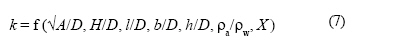
Where, the first six are the geometric variables as shown in Fig 1. Rotational speed of the rotor with six flat blades is N, g is the acceleration due to the gravity, ? is the kinematic viscosity of water and ρ aand ρ w are the densities of air and water respectively. Eq. 5 (Rao, 1999) may be expressed in terms of nondimensional parameters as follows:
Where, k = KLa20ν ( /g2) 1/3 is the non-dimensional oxygen transfer coefficient, R = ND2/ν is called Reynolds number and F = N2D/g is the Froude number. It can be expressed also as (Rao, 1999; Rao, et al., 2004):
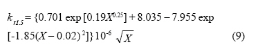
Where X= F4/3R1/3 is a parameter governing the theoretical power per unit volume. In Eq. 7, the parameter ρ /ρ is assumed as invariant; hence it can be eliminated from the analysis. The first five non-dimensional parameters represent the “geometric-similarity” of the system and the last parameter represents the dynamic-similarity. When the geometric similarity conditions are maintained, the functional relationship represented by Equation 7 is reduced toa function ofdynamic similarity (Rao, 1999) for any shape of aeration tank. k = f (X) (8) The experimental data expressed in terms of X= F4/ 3R1/3 and k=Kaν ( /g2)1/3 are plotted in Fig 2. It is quite interesting to note that the each set of data points pertaining to the given aspect ratio (1:1.5 or 1:2) of the rectangular tank fall very uniquely on a single curve. The equations governing such simulations respectively for aspect ratios 1:1.5 and 1:2 can be expressed by the following equations:
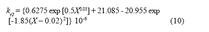
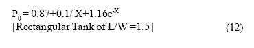
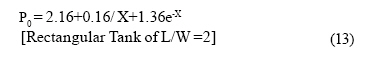
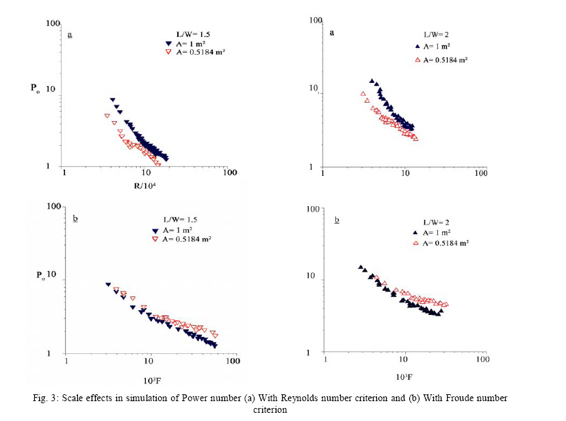
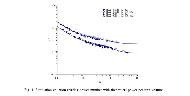
Where, kr1.5 and kr2 is the non-dimensional oxygen transfer coefficient of rectangular tanks of aspect ratios L/W=1.5 and 2 respectively. Power number The usage of power in mass transfer operations is very important while judging the performance of an aerator. The hydrodynamic conditions of surface aeration system can be characterized by interpreting power consumption of the impeller.Assuming the forces that may act on a fluid element in a tank during agitation are the viscous force FV, drag force on impeller FD, and gravity force FG, each of which can be expressed with characteristic quantities associated with the agitating system. The viscous force can be represented by the Newton’s laws of viscosity as PO =f (R, F) (11) While adopting either the Reynolds criterion or the Froude criterion, scale effects are bound to appear, as shown in Figs 3a and 3b, because neither criterion can uniquely represent the power number of the surface aerators. In other words, power number is different in different sized aerators for a given value of either the Reynolds number or the Froude number even though all the tanks are geometrically similar. It may be also noted that it is impossible to maintain a constant Reynolds or Froude number while varying the Froude or Reynolds number in geometrically similar systems, when the same fluid is used in both the systems. As discussed above, the parameter X contains both Reynolds number and Froude number and it is expressed as X = F4/3R1/3 , So the experimental data expressed in terms of power number (P0) and X are plotted in Fig 4. It is of interest to observe that for geometrically similar systems rectangular tank surface aerators, power number, P0 and X is uniquely related. Experimental data falls on a unique curve. Such a simulation curve is size independent, but different for different aspect ratios. The equations governing the simulation curves can be described by the following two equations:
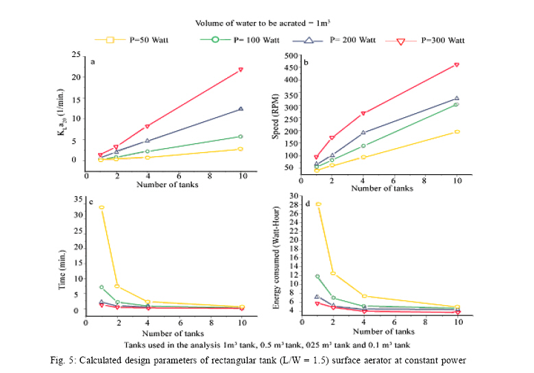
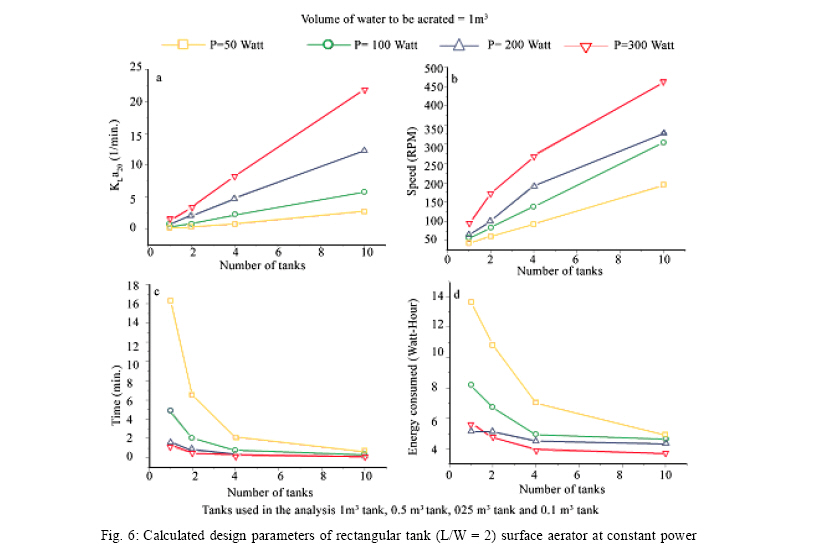
RESULTS The relations developed in Eqs. 9 and 10 and 12 and 13 (Figs. 2 and 4) for k with X and P0 with X respectively are analyzed for design purposes with an objective of searching the conditions leading to conserve the energy consumption, while choosing different sized aerator to aerate a given volume of water. It should be also mentioned here that these design curves are useful not only for scale-up but also helpful in choosing the right sized rectangular tank and appropriate dynamic conditions. Such design implications are demonstrated as follows: Example. Analyze the energy requirement to re-aerate 1 m3 volume of water by a single tank and a number of smaller sized tanks of equal volume, when each tank is subjected to a constant installed input power (P) to the shaft. The rotor is rotated until DO concentration, Ct, attains 80 % of the saturation value. The initial DO concentration C0=0 at t =0 and water temperature is assumed as constant at 25 °C. Solution: Four different sized rectangular tanks (1 m3, 0.5 m3, 0.25 m3 and 0.1 m3) of aspect ratios 1.5 and 2 are taken to analyze their energy consumption to aerate 1 m3 of water at constant input power (P), such that the numbers of tanks of each size are respectively 1, 2, 4 and10.Step 1: Geometrical parameters of the typical surface aerator as shown in Fig. 1 can be worked out by the geometric similarity condition as given in Eq. 1, step 2: The problem is solved for different assumed values of power, P = 50, 100, 200 and 300 watts. As P, D andvolume of water are known; N can be calculated from Eqs. 12 and 13 for aspect ratios 1.5 and 2 respectively by trial and error method and there from X and P0can be calculated. Step 3: The oxygen transfer coefficient, k can be computed from Equation 9 and 10, because X is known from the previous step or can be read out from Fig 2. Step 4: The value of KLa20 can be computed from k=KLa20 (ν/g2)1/3 , and KLaT from Eq. 3. Stpe 5: Time t required to achieve 80 % of saturation value is calculated from Eq. 2. Step 6: Energy is defined as the product of power and time. To aerate 1 m3 of water, it is required to employ 10 tank of 0.1 m3, 4 tanks of 0.25 m3, 2 tanks of 0.5 m3 and one tank of 1 m3 capacities. So Energy required to re-aerate the 1 m3 of water in multiple tanks is calculated as the product of total power (number of tank x power consumed) and time.As shown in Figs. 5 and 6, smaller sized tanks are consuming less energy to re aerate the same volume of water, with less time for re aeration (Figs. 5c and 6c), when compared to bigger sized tanks. One more interesting conclusion can be drawn from Figs 5 and 6 is such that even for a given size of tanks, higher the input power P, lesser the energy requirements to aerate the same volume of water, which suggests that energy can be saved substantially when the aerators of a given size are run at higher input powers (Figs. 5d and 6d). Also it can be observed that in a given size of aerator KLa20 increases as input power increases (Figs. 5a and 6a) whereas the rotor speed is also more (Figs. 5b and 6b). It is of our interest to know how much saving of energy can be achieved by using smaller sized tanks or loss of energy when bigger sized tanks are employed in aeration process to re-aerate the same volume of water. As shown in Fig. 7, by using smaller sized tanks, energy savings can be as high as about 80 % and 64 % in rectangular tank of aspect ratios1.5 and 2 respectivelywhen lower input power is given to each tank. DISCUSSION AND CONCLUSION This paper develops the simulation criteria connecting the three major parameters of oxygen transfer coefficient, k and power number, P0 and a parameter governing the theoretical power per unit volume, X (=F4/3R1/3) ingeometrically similar rectangular tanks of two aspect ratios (L/W=1.5 and 2). Simulation equations, thus developed are useful in scaling up the present results for the higher sizes. It has been found that either Reynolds (R) or Froude (F) similitude is insufficient to simulate P0. Based on the experiments, it is concluded that P0 is uniquely related to X. Equations governing P0 and X and k and X have been also developed in the present paper. Design procedures for designing the rectangular tank surface aerator have been demonstrated. It has been found that at constant input power, employing smaller sized tanks are more energy conservative than using a big sized tank, while aerating the same volume of water, thus energy saving by using smaller sized tanks is very substantial. Besides this, time for reaeration is considerably reduced while using smaller sized tanks when compared to bigger sized aeration tanks to aerate the same volume of water. NOTATION The following symbols are used in this paper: A = cross-sectional area of an aeration tank; REFERENCES
© 2006 Center for Environment and Energy Research and Studies (CEERS) The following images related to this document are available:Photo images[st06052f4.jpg] [st06052f3.jpg] [st06052f5.jpg] [st06052t1.jpg] [st06052f6.jpg] [st06052f2.jpg] [st06052f1.jpg] |
| |||||||||
