 |
| About Bioline | All Journals | Testimonials | Membership | News |
|
||||||
|
||||||
International Journal of Environment Science and Technology, Vol. 8, No. 1, 2010, pp. 31-44 Institutional scale operational symbiosis of photovoltaic and cogeneration energy systems 1M. Mostofi; 2A. H. Nosrat; 2J. M. Pearce* Department of Mechanical Engineering, Islamic Azad University, East Tehran
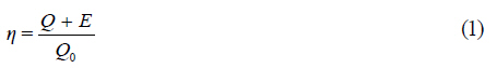
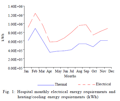
Branch, Tehran, Iran *Corresponding Author Email: pearce@me.queensu.ca Tel.: +613 533 3369; Fax: +613 533 6610 Received 25 June 2010; revised 30 September 2010; accepted 15 November 2010; available online 1 December 2010 Code Number: st11003 ABSTRACT: Due to the negative environmental effects of fossil fuel combustion, there is a growing interest in both improved efficiency in energy management and a large-scale transition to renewable energy systems. Using both of these strategies, a large institutional-scale hybrid energy system is proposed here, which incorporates both solar photovoltaic energy conversion to supply renewable energy and cogeneration to improve efficiency. In this case, the photovoltaic reduces the run time for the cogeneration to meet load, particularly in peaking air conditioning times. In turn, however, the cogeneration system is used to provide power back up for the photovoltaic during the night and adverse weather conditions. To illustrate the operational symbiosis between these two technical systems, this study provides a case study of a hybrid photovoltaic and cogeration system for the Taleghani hospital in Tehran. Three design scenarios using only existing technologies for such a hybrid system are considered here:1) single cogeneration + photovoltaic, 2) double cogeneration + photovoltaic, 3) single cogeneration + photovoltaic + storage. Numerical simulations for photovoltaic and cogeneration performance both before and after incorporating improved thermal energy management and high efficiency lighting were considered. The results show that the total amount of natural gas required to provide for the hospitals needs could be lowered from the current status by 55 % for scenario 1 and 62 % for both scenarios 2 and 3, respectively. This significant improvement in natural gas consumption illustrates the potential of hybridizing solar photovoltaic systems and cogeneration systems on a large scale. Keywords: Combined heat and power; Distributed generation; Hybrid energy system; Photovoltaic INTRODUCTION Anthropogenic climate destabilization has evolved to a point to be an immediate threat to human welfare, global ecosystems and the temperate climate for which life on earth has evolved and human society's were formed (IPCC, 2007a). The global green house gas (GHG) emissions from human sources, have risen to 49 GtCO2-eq/y precipitating a concomitant increase in atmospheric carbon concentration from a pre-anthropocene level of 280 ppmv to 379 ppmv in 2005 (IPCC, 2007b). These GHG emissions are primarily caused by the combustion of fossil fuels such as coal, oil and natural gas. However, the majority of the primary energy in fossil fuels is still wasted during conversion to electricity in power plants (Hawken et al., 1999; ISIRI, 1999; Masarat, 2004; Sirchis, 2005; IEA, 2008a; Igwe et al., 2008; Zvindoanda et al., 2009; Karapidakis et al., 2010). The top climate change science now recommend that in order to avoid further disruption to the thermal equilibrium of the planet and avoid additional negative effects on human society, GHG emissions be stabilized at levels below 350 ppmv (Hansen, et al., 2008). There are two clear strategies to reduce GHG emissions: 1) use fossil fuels more efficiently and 2) use renewable energy technologies, which do not directly emit GHGs during energy conversion, to offset emissions from conventional coal, natural gas and oil-fired electrical power plants (CHP) (Sayigh, 2000; Sims et al., 2003; IPCC, 2007b; IEA, 2008a; IEA, 2008b; IMOE, 2008; Refaat et al., 2008; Refaat, 2009; Panjeshahi and Ataei, 2008). Considering strategy 1 The most straight forward method of increasing the efficiency of electric generation with fossil fuels is to utilize the `waste heat' from production with cogeneration. The cogeneration of heat and power is a superior method of energy management because `waste' heat can be used either for space or water heating or with the addition of an absorption chiller for cooling in so called `tri-generation' systems (Tozer et al., 1996; Hernández-Santoyo and Sánchez-Cifuentes, 2003; Miri et al., 2003; Hennicke, 2005; Samarghandi et al., 2007; Refaat et al., 2008; Shah et al., 2009). CHP systems have several advantages over conventional supplies of energy (Pilavachi, 2000; Pilavachi, 2002; Miri et al., 2003; Sirchis 2005; Karapidakis et al., 2010) such as 1) decrease in primary energy consumption and thus decrease in energy costs; 2) reduce the transmission and distribution losses; 3) decrease need to establish new power plants and selling the electricity to the network; and 4) decrease in environmental emissions. Even with the efficiency increased these technologies are still GHG emitters, which contribute to climate destabilization, and thus their use should be minimized. Considering strategy 2 One of the most promising renewable energy technologies, with nearly world wide geographic distribution is solar photovoltaic (PV) cells, which convert sunlight directly into electricity and possess well-established environmental benefits (Pearce, 2002). However, PV cells are held back by technical limitations due to the inherent intermittency of the solar resource, which makes deploying PV alone unable to fully replace a new power plant operated in base load without considerable electrical storage (Jochem et al., 2002). Recent previous work has shown that when CHP and PV technologies are coupled together each technology fortifies the others weaknesses (Derewonko and Pearce, 2009; Pearce, 2009a; Pearce, 2009b). In particular, the penetration level of PV can be increased with the use of small household scale hybrid PV+CHP systems (Derewonko and Pearce, 2009; Pearce, 2009a; Pearce, 2009b). To build on this previous work to assist the transition from inefficient fossil fuel-based energy management to renewable energy systems using both of these strategies, a large institutional-scale hybrid energy system is proposed here, which incorporates both solar PV and cogeneration. To illustrate this symbiotic technical system, this paper provides a case study of a hybrid PV and cogeneration system for the Taleghani hospital in Tehran. Three design scenarios for such a hybrid system are considered which use only existing technologies. These scenarios are optimized with numerical simulation for energy efficiency and results for both the thermal and electric systems performance are provided. Data collection took place in the year 2007 in Tehran and the simulation and analysis took place in the summer of 2009 at the Mechanical and Materials Engineering Department of Queen's University in Ontario, Canada. MATERIALS AND METHODES The solar PV component of the case study is simulated via PVSYST ver. 4.37, using solar flux and temperature data from the Iranian Association of Solar Energy. Monthly electrical and thermal loads of the hospital have been acquired from energy bills over a year. The CHP systems in the three scenarios are designed based on thermal load demands. It is assumed that irregular energy peaks will be supplied by auxiliary generator and/or boilers. Finally, excess electrical energy is assumed to be fed back onto the grid. Taleghani Hospital, known to have 400 beds in an area of 33,621 m2, is capable of providing general surgery while specializing in surgery for the ear, throat and nose. The hospital also focuses on urology, gynecology, optometry and women's health care. The energy load of the building can be attributed to three subsystems of lighting, heating ventilation and air conditioning (HVAC) and general equipment including computers, TVs, kitchen, laundry and medical equipment. The hospital receives its energy primarily through natural gas, electricity and in emergency situations, oil. The monthly electric and thermal loads of the hospital are presented in Fig. 1. Basic design of a hybrid PV+CHP system CHP overview Usually, the required electricity for industrial units, commercial and residential buildings in Iran is supplied by conventional steam power plants operating at ~35% conversion efficiency, where the residual heat will be lost usually in cooling towers (Kroger, 2003; Sirchis, 2005). These efficiencies can be increased significantly by producing the electricity on site and using the `waste' heat in the building for its needs. The effect of this cogeneration, on one hand results in a slight decrease in electrical generation efficiency, but on the other hand, it will result in considerably less consumption of fuel used for supplying required heat and its associated costs (Benelmir and Feidt, 1998; Petchers, 2003; Hennicke, 2004; Sirchis, 2005). Today, because of advances in technology, CHP systems with any size and application are feasible. In a CHP system, a prime mover such as engine or turbine releases the chemical energy of the fuel and converts it to electrical power. The maximum efficiency for the machine prime mover is about 50 % and thus half of the primary fuel energy is lost as wasted heat. In this kind of system, sources for this waste include exhausted gases from prime mover, cooling cycle and cooling oil. Using heat exchangers, this heat can be recycled as a high temperature fluid. The typical efficiency for an electricity generator and a boiler are about 35 % and 90 %, respectively (Petchers, 2003; Sirchis, 2005). Using the CHP system, which has both of the prescribed machines achievements, efficiency can be higher than 85 % (Petchers, 2003; Sirchis, 2005). Thus, the electrical efficiency for the machine is 35 % and thermal energy efficiency is about 50 %. Less fuel consumption is very clear in this scheme. The total efficiency for a CHP system is given by:
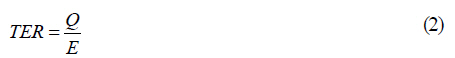
Where Q and E represent utilized thermal and electrical energy, respectively and Q0 shows the heat content of the fuel. In general, E is either consumed by the load or fed back into the electricity grid. However, Q must have an acceptable quality, quantity and temperature to generate hot water and steam. A CHP system can be defined in both topping and bottoming cycles. In the topping cycle, the fuel is burned to drive a generator which is established to generate electricity. This generated electricity can be either consumed locally or sold off site. Exhausted gases will be lead to a heat recovery boiler to supply steam or hot water. While in the bottoming cycle, which is mostly used in processes, first high temperature gases are used in the process and then, low temperature gases are utilized to generate electricity. For non-industrial buildings like hospitals and hotels, topping cycles are more technically and economically viable. The primary components of a CHP system are prime movers, electrical controls, heat regenerating devices, and absorption chillers. CHP prime movers are defined by a thermal to electrical power ratio (Pilavachi, 2000; Sirchis, 2005):
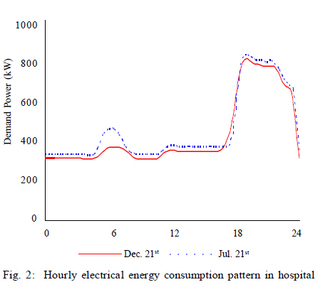
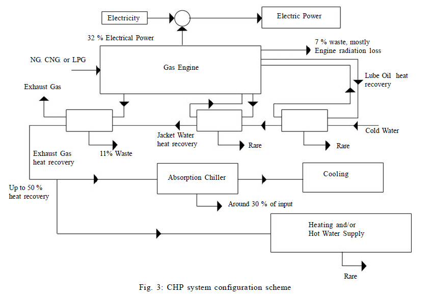
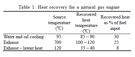
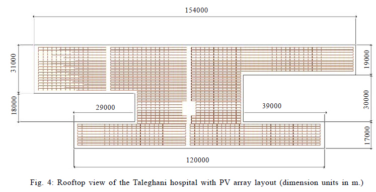
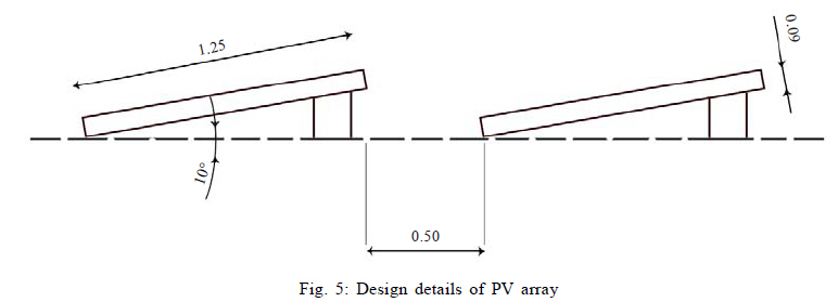
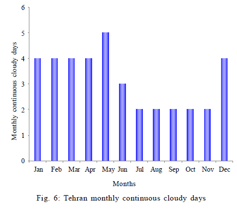
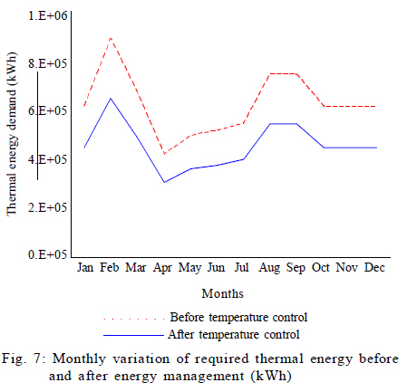
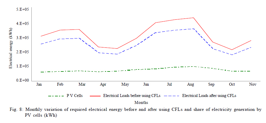
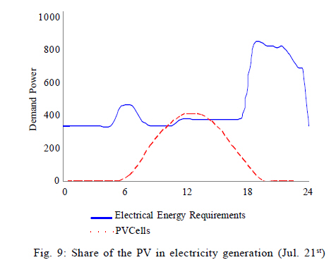
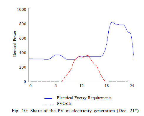
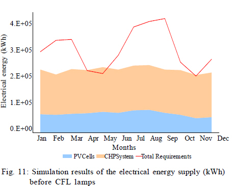
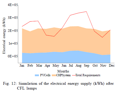
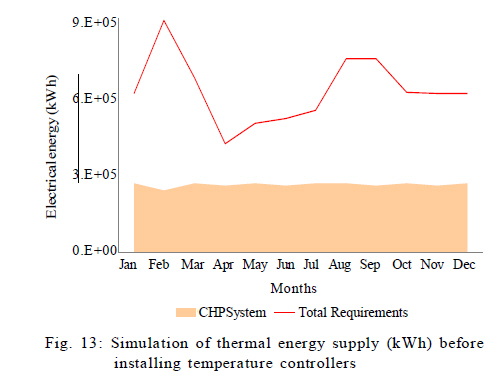
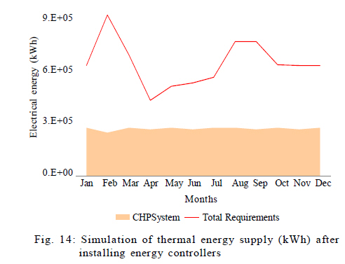
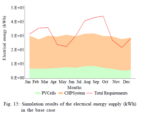
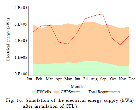
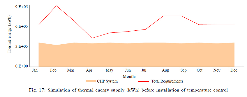
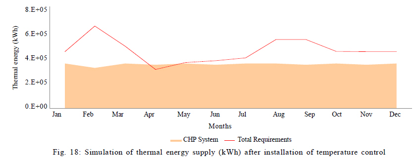
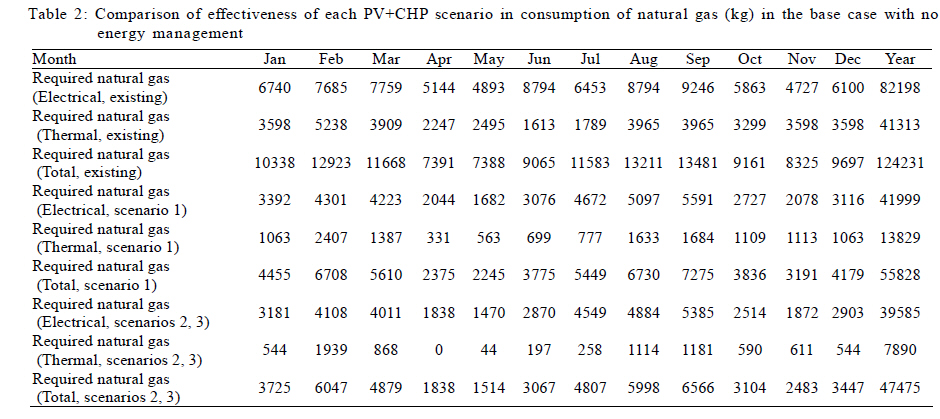
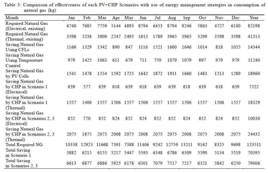
Proposed CHP system The hourly electrical load of the hospital for both summer (July 21st) and winter (December 21st) loads are presented in Fig. 2. The base load of the hospital can be identified at about 300 kW. It is of further interest to recognize that hours 18 to 24 witness a drastic intermediary load identified at a peak of about 600 kW. This huge increase in evening can be attributed to an increase of active lights throughout the building, which would then be brought back to regular conditions by midnight. It is also noted that the similar winter and summer loads are attributed to the use of natural gas coolers which would relieve the burden of added cooling in the summer (Fig. 2). In this research, a spark ignition reciprocating engine that operates on natural gas and air has been utilized. The parameters of the engine performance are as follows: electrical efficiency (32 %), water cooling system loss (30 %), exhaust gas losses (28 %), engine radiation loss (7 %), oil cooling loss (2 %) and other losses (1 %) (Miri et al., 2003). While most engine parameters are variable with time, the numbers listed are the most common values in the lifetime of an engine. Thermal energy can be recovered in this engine via the oil chiller, water chiller and exhaust heat. While thermal energy from the water cooling system is better used to generate hot water, heat from the oil chiller and exhaust gas are more effective at supplying low pressure steam. The exhaust heat can reach up to values of 700 oC in temperature when recovered, can lead to significantly reduced NOx emissions. The primary heat recovery methods for all three components are typically "shell and tube heat exchangers". Fig. 3 shows a schematic diagram of the CHP system configuration. Electrical efficiency obtained by natural gas engines have been reported in the range of 30 40 % (Miri et al., 2003; Kong et al., 2005). In such CHP systems, thermal to electrical energy ratio in these engines is in the range of 1 to 2 (Miri et al., 2003; Kong et al., 2005). In these engines, up to 90% of the heat loss from engine can be recycled as hot water or low pressure steam. Table 1 illustrates the recovery capacity of a typical natural gas engine such as the one in this case study. According to (Wang, 2000), the recovered heat Qex,r can be calculated as: Qex, r = Vex ρex cpa (Tex - Trec) Where Vex, ρex, cpa, ,Tex and Trec represent volume flow rate of exhaust gas at outlet of gas engine (m3/s), density of exhaust gas at outlet of gas engine (kg/m3), specific heat of exhaust gas (j/kg.oC), temperature of exhaust gas at outlet of gas engine (oC) and temperature of exhaust gas leaving the heat recovery heat exchanger (oC), respectively. In some configurations of heat recovery from the exhaust heat, the process is done in two stages. In the first stage, hot water or low pressure steam is captured by a shell and tube heat exchanger, a feature that is common in all types of CHP heat recovery systems. An additional stage could be included where fluid temperature is lowered to 120 oC and if required, another condensing heat exchanger can recover additional heat. These two steps can recover 50 60 % of the fuel energy content of the system. In the case of reciprocating engines which are cooled by cooling liquid, this liquid is a secondary resource for heat recovery. To optimize the CHP heat recovery component, it is necessary to use the thermal loads of the Taleghani hospital. According to energy bills obtained from the hospital, the entire building consumes 13,140 m3 of hot water per annum requiring an estimated 762,120 kWh of thermal energy. Previous work includes (Arghandeh, et al., 2007) modeling a small gas engine coupled cogeneration system for a relatively large hospital in Tehran. The CHP system, also designed for a peak load of 18-24, two scenarios have been proposed to reduce the energy consumption of the hospital. The first scenario utilizes a generator that only provides a base load for the hospital, while the second scenario an additional generator is used for peak loads. The second scenario has proven to be more effective in improving the energy efficiency, especially in light of the government's efforts to phase out energy subsidies. Furthermore, the need for natural gas to heat chemical refrigerants has been eliminated (Kolanowski, 2003). Other case studies include work done by (Thirakomen, 2001) on a power plant in Thailand utilizing cogeneration absorption chillers. Thirakomen (2001) claims that electricity costs have been reduced by 35 % . Another case includes a CHP system in Nigerian villages (Nwanya, 2005). Proposed PV system Grid-connected PV systems typically consist of the PV panels themselves which convert photons from the sunlight into electricity through the photovoltaic process. There are three major types of PV panels on the market in the order of increasing efficiency and cost: thin films (amorphous silicon, cadmium telluride, and copper indium disellinide), polycrystalline silicon and monocrystalline silicon. The direct current (DC) output of the process, however, is unsuitable for alternating current (AC) electric grids. This problem is overcome with the introduction of inverters that convert DC to AC power. Modern inverters typically have conversion efficiencies greater than 90 % (Messenger and Ventre, 2004). Other system components usually include circuit breakers, wiring and racking. Taleghani hospital, shown in Fig. 4, has an ample amount of roof space that can be utilized for the installation of PV modules. The system was designed with a tilt angle of 10 degrees to ensure self-cleaning with rain without financial penalties resulting from the necessary BOS needed to protect against higher wind loads with more energetic optimized tilt angle (the optimal angle in Tehran angle for yearly energy production is 33 o, in summer it is 13 o, and winter 55 o) as seen in Fig. 5. The adjacent PV rows were place at 0.5 m apart to allow space for maintenance crew to repair and clean the modules effectively. The system also has been designed to allow for approximately 2 m between the edge of the roof and the closest PV module. Pathways have been incorporated into the system for maintenance. The module type incorporated in the design is a Schueco S 340-PM-2 monocrystalline panel. The module has a rated power of 341.1 W and efficiency of 12.6 % (there are considerably more efficient panels on the market e.g. Sanyo HIP with 17.21% but the PV system was sized to utilize the roof space and match the CHP systems). The array consists of 176 strings at 9 modules per string. The array design is such that it allows walkways for maintenance and upkeep. The total array size consisting of 1591 solar modules (and no inverters) is considered to occupy some 4,270 m2 of the roof space. Simulation based on PVSYST reveals that this system can produce approximately 850,000 kWh/y. Based on solar radiation maps obtained from the Iran's Renewable Energies Organization (SUNA), Iran shows strong solar fluxes within its borders (SUNA 2010). Despite this great resource, solar energy has failed to find its right place in Iran's energy market. The Iranian Renewable Energies Organization is currently only working on less than a dozen pilot photovoltaic projects and has only initiated one industrial scale solar thermal (250 MW) plant in Shiraz. In addition to the abundant solar irradiation available, interventions with system performance are minimal due to low monthly continuous cloudy days, as depicted in Fig. 6 (shows Tehran data only) (SUNA, 2010). Therefore, PV technology in Iran can be a great mechanism for ameliorating the high GHG emissions, as well as reducing dependencies on fossil fuels. The location of the site in Tehran does not have the most ideal amount of solar flux within Iran, but is home to the largest urban population in the country. Tehran is located 35.4 ºN and 51.21 º E at an average altitude of 1900 m above the sea level. Hourly and monthly solar flux has been obtained by the meteorological efforts of (Samimi, 2002) and is based on the Gregorian calendar. Design of PV CHP system thermal energy In any energy design case, energy efficiency should be considered first. It should be noted that both the actual thermal and electrical consumption of the hospital is highly inefficient and an earlier investigation revealed several methods to reduce energy consumption in the hospital (IEEO, 2000). Two energy conservation measures were considered. First, installing a heat control mechanism can increase the thermal consumption efficiency by 27.2 % with a payback time of 0.1 y (IEEO, 2000). Considering the fact that PV only provides electrical energy, the thermal energy supply is provided by the CHP system. Thus, the CHP component is optimized based on the thermal energy requirements of the hospital (Fig. 1) and considering the fact that, hospital needs continuous service hot water and heating or cooling energy (using the degree day technique), Fig. 7 is generated showing the thermal energy (kWh) needed throughout the year. In Fig. 7, in addition to the thermal energy consumption for building in the base case that is shown by solid line, thermal energy demand after installing the temperature control of the cooling and heating system is expressed in dashed line. As mentioned before, one of the advantages of choosing a natural gas engine is due to its favorable thermal to electrical energy ratio. As stated before in equation, TER of a typical natural gas engine is approximately 1.56, nearly ideal for this application as shown in Fig. 7. The second energy conservation measure (ECM) considered was a lighting retrofit with compact fluorescent light (CFL) bulbs, which ¼ the energy to produce the same amount of light as a standard incandescent light bulb. CFL bulbs fit in the average light socket, last longer, and cost less over their lifecycle than incandescent bulbs (Pearce and Russill, 2005). In the hospital case this leads to a 17.3% in electrical energy consumption and a payback time of 0.2 years (IEEO, 2000). The simulated electrical performance of the PV system based on solar flux data for Tehran from SUNA has also been determined on a monthly basis. The PV power output (dash dotted line) is also presented in Fig. 8, along with the improved electric consumption of the hospital before (solid line) and after (dashed line) the installment of CFLs. Daily performances of the PV component for summer (July 21st) and winter (December 21st) terms are presented and compared to improved daily electric loads in Figs. 9 and 10. As can be seen in Figs. 9 and 10 the peak output of the array is closely aligned at solar noon with the demand. As can be seen in Figs. 9 and 10, Jul 21st has a PV energy production of 2,432 kWh, while December 21st produces about 13 % less with 2, 104 kWh. During the summer, the demand throughout the day is about 10,780 kWh and 10,270 in the winter. Thus, the PV array provides about 22.5 % of the necessary electrical requirements in the summer and 20.5 % in the winter. Design scenario 1: Single CHP + PV This scenario incorporates a CHP engine capable of matching the 300 kW base load of the hospital. Such an engine is expected to have a thermal output of around 470 kW and up to 330 kW of cooling loads can be extracted by this system via absorption chillers. Assuming, the PV component can provide an aggregated peak of electricity generation for about 6 h/day, a parallel 300 kW CHP engine will provide 5,400 kWh/day to cover the shortcomings of PV electric generation. It is expected that the CHP engine will operate at limited capacity during PV electric generation times while operating at full capacity during nighttime. This scenario will suffice for covering the base load of hospital load. Figs. 11 and 12 depict the energy loads and production of the hospital before and after implementing the CFL lamps. As can be seen in Fig. 11, only briefly in April-May does the electrical production of the hybrid system surpass the total load of the hospital. This 27,000 kWh will be fed back unto the grid. In this case the hybrid system can provide 7 6 % of the total load of the hospital. This can be improved considerably to 91% when the energy efficiency retrofit is accomplished. However, now 161,000 kWh are returned to the grid as in April-June and October-November the hybrid PV+CHP system produce more electricity than the hospital requires. Likewise, the thermal energy load and supply before and after the installation of temperature controllers for energy management are presented in Figs. 13 and 14. In the case, without energy management the CHP system provides 42 % of the hospital's heating load as can be seen in Fig. 13. Although, in Fig. 14, this is increased to 57 %, this is still inadequate. Design scenario 2: Double CHP + PV In this scenario, which is more effective in one hand and more costly on the other hand, another 300 kW engine can be utilized in order to cover the peak loads between 18 and 24. This scenario is considerably more complicated as two CHP unit controls need to be coupled and will have a higher cost of maintenance associated with running two systems. Similar simulations as were described for scenario 1 have been applied and are presented in Figs. 15, 16, 17, 18. First in Fig. 15, the base case electrical production is shown. Here the PV+CHP hybrid system provides 93% of the load and an excess of 227,000 kWhs throughout the year, which will be fed back onto the grid. After the energy efficient lighting retrofit the system provides 112 % with an excess of 530,000 kWhs as seen in Fig. 16. The electrical load is only not met by a small amount in February and a period from July-Sept. This is a far better electric supply-demand matched system than in scenario 1, but as the hospital is still connected to the grid the total load following is not necessary, although matching as close as possible is ideal for economic and PV penetration considerations (Pearce, 2009a). In the case of heat, because it can't be stored the ideal will be to meet the load as closely as possible on the least demanding month. As can be seen in Fig. 17, without energy management only 56% of the thermal load is met and the PV+CHP system still does not match the load even in April. However, as can be seen in Fig. 18, using the PV + CHP system, the load is met nearly perfectly in April and May and the percentage of heat supplied for the hospital has increased to 76 %. Only 7,502 kW-hrs are vented. Design scenario 3: Single CHP + PV + Storage In the third scenario, electricity generated from PV is stored and utilized from hours 18 to 24 to cover the peak loads with a single generator providing a base 300 kW load. This design has results that are almost identical to the electric loads and supplies of scenario 2 with the thermal loads and supplies of scenario 1 despite being fundamentally different in layout from the other scenarios. Scenario 3 is devoid of the technical shortcomings and the low performance of scenario 1 as well as the complexity and high cost for the CHP systems of scenario 2. However, the controls and batteries necessary to smooth out the electrical load are considerable. Almost all of the electrical energy can be supplied by this system and in the event of surpluses, revenue can be generated from selling the extra electricity back to the grid. An unfortunate shortcoming of this design is the relatively low thermal supply made available to the hospital. RESULTS AND DISCUSSION The CHP component of the system is designed to operate on natural gas as long as there is enough availability. Other sources of fuel can be used in times of emergency, shortages, or as global policies shift to reduce the effects of greenhouse gas emissions a source such as biogas can be used. This paper, however, assumes that the CHP units are operated entirely by natural gas. Considering that Tehran's power plants are primarily supplied by natural gas (IMOE, 2005; Atabi, 2004) as well, it is desirable to provide electricity on site rather than at a power plant which will then have associated distribution losses of 26.7 %. Knowing that the average efficiency of Iranian power plants is 36.2% (IMOE, 2005), the real efficiency of electricity generation in Iran is at 26.5%. Therefore it is highly beneficial to generate electricity locally and away from the electric grid because CHP electrical efficiencies alone are 32 %. If it is assumed that only natural gas is used as the fuel to provide both heat and electricity the percentage savings on fuel for use of the energy management strategies and the three PV+CHP system scenarios can be calculated. This is done in Table 2, for the conventional case, and Table 3 for the cases involving the use of energy management strategies. As it can be shown in Table 2, if scenario 1 is chosen, the total amount of natural gas required would be 44.9 % of the required natural gas in existing situation. Savings of the electrical and thermal energy are combined as natural gas is consumed for both electrical and thermal energy supplies. In addition, in scenario 2 or 3 the savings improve and required natural gas will be only 38.2 % of the natural gas required for the existing situation. As Table 3 shows, the savings of each sub-strategy (effects of using PV cells, CFLs and central temperature control system) are reported separately. As it can be seen in Table 3, by using PV cells, 18, 960 kg NG will be saved annually, which is 23.1% of the total amount of natural gas required for electricity generation. In addition, by using CFLs and temperature control strategies 17.5 % of the electrical energy requirements and 27.2 % of the thermal energy requirements are reduced respectively. With a simple comparison, it will be clear that, by using scenario 1 or each of scenarios 2 or 3, natural gas consumption will be lowered from the status quo by 55 % and 62 % respectively. This significant improvement in natural gas consumption leads to a savings of 68,400 and 76,700 kg NG respectively. Based on CHP efficiency definition on one hand and using the electrical and thermal energy efficiency of the current CHP systems, the CHP efficiency can be rewritten as ηCHP = ηE + ηT= 0.32 + 0.50 = 0.82. This efficiency is applicable when all the supplied energy can be utilized. In most of the results, because of huge amount of required energy, all the supplied energy is usable. In scenario 1, the CHP efficiency will be exactly 82 % as mentioned before. However, in scenarios 2 and 3, based on Fig. 18, in April, it is mentioned that, around 171 kg NG will be lost as excess amount of heat is generated. If this amount of heat loss is considered, CHP efficiency will be affected. Based on the calculation, this loss is not significant and consequently, the efficiency will be about 81.7 %. It is clear, in this case, the loss is very tiny and the CHP system works in the near ideal situation. It should be mentioned here that the financial considerations for this project should be considered before implementation. This article has demonstrated the technical feasibility and energy advantage of installing a hybrid PV and cogen system for a particular hospital application. However, Iran's rapidly changing energy and technology market warrants an appropriate financial study and sensitivity analysis for the implementation of the proposed solution. This economic study is left for future work. Issues such as technological availability in Iran's emerging PV and cogen industries, as well as the installation costs of the balance of system components, wiring, controls, inverter, legalities, fuel, emissions and cost reductions both locally and on the grid are but a few parameters to be considered in such an investigation. This is all the more useful as Iran's energy subsidy program is going through its most drastic transformation in the past 30 years. Conclusion This study has demonstrated that the large institutional-scale hybrid energy system proposed here, which incorporates both solar photovoltaic energy conversion to supply renewable energy and cogeneration, can be used to radically improve energy performance. Assuming that the energy source is natural gas, the results show that the total amount of natural gas required to provide for the hospitals needs could be lowered from the current status by 55 % for scenario 1 (PV + single cogen) and 62 % for both scenario 2 and 3 (double cogen + PV or hybrid cogen + PV + reduced size of storage), respectively. The efficiency of the cogeneration system when fully utilized is 82 %, which is met in scenario 1 and for scenario 2 and 3 the efficiency only drops by 0.3 %. It is clear that the solar photovoltaic array deployed on the hospital roof reduces the run time for the cogen to meet load and thus directly reduces natural gas use and greenhouse gas emissions. In turn, however, the cogen system is used to provide power back up for the PV during the night and adverse weather conditions to radically reduce the size of storage necessary to provide electrical demands (or as in the case of scenario 2, completely eliminate it). This research clearly illustrated the operational symbiosis present when coupling these two technical systems and also reinforced the need to ensure optimal thermal energy management and high efficiency electrical devices. The significant improvement in natural gas consumption shown here illustrates the potential of hybridizing solar photovoltaic systems and cogeneration systems on a large scale to improve energy and environmental performance. ACKNOWLEDGEMENTS The authors would like to acknowledge the support of the Queen's University Principal's Development Fund, Iranian Modern Energies Organization (SUNA), and Natural Sciences and Engineering Research Council of Canada for this work. REFERENCES
© IRSEN, CEERS, IAU The following images related to this document are available:Photo images[st11003f8.jpg] [st11003f4.jpg] [st11003f13.jpg] [st11003f9.jpg] [st11003f7.jpg] [st11003f18.jpg] [st11003f10.jpg] [st11003t3.jpg] [st11003t1.jpg] [st11003f12.jpg] [st11003f2.jpg] [st11003f16.jpg] [st11003f17.jpg] [st11003f6.jpg] [st11003f11.jpg] [st11003f3.jpg] [st11003f5.jpg] [st11003f1.jpg] [st11003t2.jpg] [st11003f15.jpg] [st11003f14.jpg] |
| |||||||||
