 |
| About Bioline | All Journals | Testimonials | Membership | News |
|
||||||
|
||||||
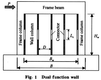
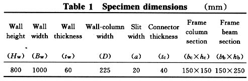
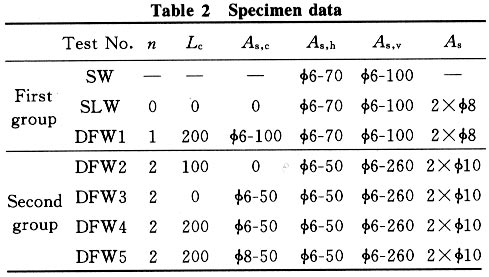
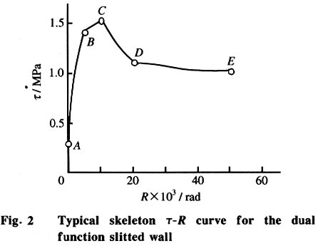
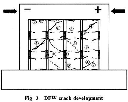
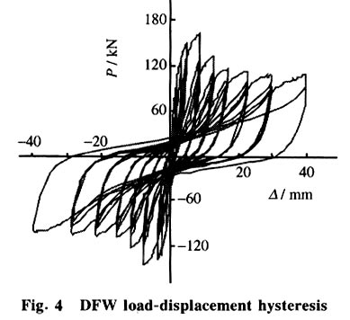
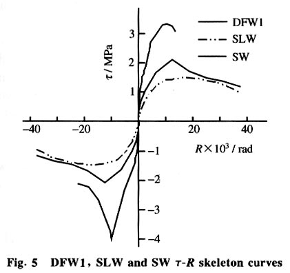
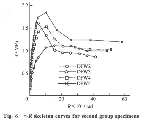
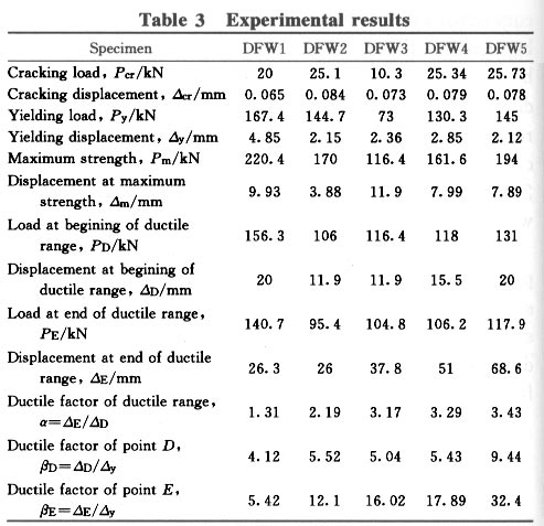
Seismic Behavior of Dual Function Slitted Shear Wall* YE Lieping Department of Civil Engineering, Tsinghua University, Beijing 100084, China * Supported by the National Natural Science Foundation of China (No. 59678029) Received: 1999-12-15; revised: 2000-10-30 Code Number: ts01096 Abstract: The concept of seismic structural control was used to design a new type reinforced concrete shear wall, the dual function slitted shear wall. Connectors are installed in vertical slits in the slitted shear wall to provide the dual function slitted shear wall with greater stiffness and capacity for small and moderate earthquake intensities. The wall becomes a slitted wall with the ductile flexure failure mode when the connectors fail during severe earthquakes. Seven specimens were tested to study the seismic behavior of the dual function slitted shear wall. The results showed that the connector controlled function well and provided better seismic behavior Key words: reinforced concrete; slitted wall; connector; seismic control Introduction To improve the brittle shear failure of solid shear walls (SW), Muto[1] suggested a slitted wall (SLW) which can develop ductile flexure failure. But the initial lateral stiffness is much less than that in a solid wall due to the slit, which may result in some problems of displacement control for the service ability limit state. Both larger initial stiffness and larger ductility can be obtained by adding a set of connectors to the slitted wall. This new type shear wall, called a dual function slitted shear wall (DFW) (Fig.1), was proposed based on the concept of seismic structural control[2]. With the connectors, the wall performs like a solid wall with larger stiffness under service load and during small earthquakes (Function 1). The connectors fail or yield during severe earthquakes so that the wall then automatically performs like a slitted wall with a ductile flexure failure mode (Function 2). The damage during moderate earthquakes is mainly confined to the connector which is easy to be repaired. 1 Specimens Seven specimens were tested to study the seismic behavior of dual function slitted walls. All of the specimens have the same dimensions, as shown in Table 1. The main research parameters are the stiffness ratios and the strength ratios of the connector to the wall-column and the connector arrangement. The specimens were divided into two groups. The first group had DFW1, SLW and SW for comparison. The three specimens have almost the same amount of reinforcement. The specimens in the second group were all of dual function slitted walls to study the detailed seismic behavior including load carrying capacity, lateral stiffness, deformation capacity, ductility, and hysteresis behavior. The specimen parameters are listed in Table 2. The specimens were tested using lateral cyclic loads at the frame beam axis. The crack development at the connector and wall-column was observed as the load increased. The lateral displacement and relative vertical displacement between the slit at the connector position were measured. All test data were recorded automatically. 2 Behavior of Dual Function Slitted Wall Figure 2 shows a typical t-R skeleton curve for the dual function slitted wall under lateral loading, where t=P/A is the average shear stress across the horizontal section of the wall and R=D/Hw is the drift angle. Analysis of the test results showed the following characteristic behavior for the dual function slitted wall: (1) Elastic stage (0A) First crack ((1) in Fig. 3) was usually observed at the connector due to shear stress[3,4]. Before cracking, the dual function slitted wall was in the elastic stage. In this stage, the behavior of the dual function slitted wall is like a solid wall with large lateral stiffness, about 2 - 3 times larger than that of the corresponding slitted wall[5]. (2) Elasto-plastic stage after cracking of connector (AB) The flexure moment caused horizontal cracks ((2) in Fig. 3) to occur at the top and bottom sections of the wall-columns. With increasing load, more shear cracks were observed in the connectors. At about 50% Pu (here Pu is the maxium load capacity), the crack width in the connectors was about 0.1-0.2 mm. The setting of connectors resulted in a large flexure stress at the wall-column cross sections near the connectors, which caused horizontal cracks ↙; and the small shear span ratio of the wall-column segments caused some shear diagonal cracks (3) to occur. (3) Yielding of wall-column As the load increased, the top and bottom sections of the wall-column yielded (Point B in Fig. 2). (4) Connector failure (BCD) After the yielding of the wall-columns, the connector shear cracks developed rapidly and the connector concrete began to crash as the load approaching the maximum. The connector shear stiffness decreased as more cracks developed and the concrete crashed, which resulted in less connection with the wall-column. It was observed that cracks ↙ and (3) did not develop at this stage. After the maximum strength, the load carrying capacity quickly decreased as the connector crash. After the connector concrete fully crashed (point D in Fig. 2), the wall became a slitted wall except for some remaining steel bars passing through the connectors. (5) Ductile loading stage (DE) After the connector concrete was totally crashed and the wall became a slitted wall, the load carrying capacity became stable again. In this stage, the deformation capacity was larger. Due to the remaining steel bars in the connectors, the load carrying capacity in this stage was about 10%-20% higher than that of the corresponding slitted wall. Figure 3 shows the typical cracking formation process in a dual function slitted wall. It can be seen that the final failure pattern was almost the same as that of a slitted wall. The load-displacement hysteresis relation of the dual function slitted wall is shown in Fig. 4. 3 Comparison with Solid and Slitted Wall Figure 5 compares the t-R skeleton curves of DFW1, SLW, and SW. Among these three specimens, the SW had the largest initial lateral stiffness and strength with brittle shear failure mode after the maximum strength. The SLW had the lowest initial lateral stiffness and strength with ductile flexure failure mode. The initial lateral stiffness and strength of the DFW1 was found between the solid wall and the slitted wall. The DFW1 t-R skeleton curve was similar to that of SLW after a decreasing load from its maximum strength due to the connector failure. The DFW1 failure mode was almost the same as that of SLW. 4 Experimental Results 4.1 Lateral stiffness The lateral stiffness of the dual function slitted wall was high for small deformations and decreased greatly under large deformations. Compared with specimen SLW, the initial lateral stiffness of DFW1 was about 3 times that of SLW before the connector cracking. After the connectors totally failed, the equivalent lateral stiffness of DFW1 was almost the same as that of SLW, which was only about 1/50 of its initial value. The connector in the dual function slitted wall can provide the proper stiffness control for different earthquake intensities. For small earthquakes, the wall stiffness is large due to the connector so that the structural deformation can be easily controlled within the design criteria. Under severe earthquakes, the stiffness was decreased greatly, which resulted in less earthquake force response as the wall reverted to a ductile failure mode. Figure 6 shows the t-R skeleton curves for the second group specimens. The DFW3 connectors were made of only steel bars, while the DFW4 connectors were made with concrete and the same steel bars in the DFW3 connectors. Comparing DFW3 with DFW4, the connector shear stiffness greatly influenced the lateral stiffness of the dual function slitted wall. The DFW3 specimen performs more like a slitted wall with a slightly increasing load carrying capacity due to steel connector. DFW4 with a larger shear stiffness of the concrete connector had a larger stiffness and load carrying capacity than that of DFW3, but with the same load carrying capacity and deformation capability as that of DFW3 in the ductile loading range. The initial lateral stiffness of DFW2, DFW4, and DFW5 was almost the same because of the same connector shear stiffness in these specimens. As the load increased to about 50%Pu - 70%Pu, the lateral stiffness was about 20% - 30% of the initial lateral stiffness and about 10% of the initial lateral stiffness at maximum strength. After the connector crashed, the lateral stiffness in the ductile loading range was only about 2% - 3% of the initial lateral stiffness. 4.2 Load carrying capability As shown in Fig. 5, the maximum strength of the DFW1 was less than the SW but larger than the SLW. The maximum strength of DFW1 was about 40% higher than SLW with a slightly higher load carrying capacity than SLW in the ductile loading range. The ratio of the connector stiffness to the wall-column stiffness is the main parameter affecting the maximum strength of the dual function slitted wall, Fig. 6, while the reinforcement in the connector affects the load carrying capacity in the ductile loading range. The connector of specimen DFW2 was only made of concrete without reinforcement. Although the maximum strength of DFW2 was larger, the load carrying capacity quickly decreased after the connector crashed. The DFW3 specimen has only reinforcement bars in the connector, so the maximum strength was not high but it has a much larger load carrying capacity than that of DFW2 in the ductile loading range. With concrete in the connector, the maximum strength of DFW4 was 38.8% higher than that of DFW3 and the load carrying capacity in the ductile loading range was almost the same as that of DFW3. Increasing the reinforcement in the connector caused DFW5 to have a higher maximum strength and load carrying capacity in the ductile loading range than that of DFW4. The main experimental results for the dual function slitted wall specimens are listed in Table 3. 4.3 Ductility Because the dual function slitted wall is a seismic control structure, the traditional ductility evaluation is not suitable. In the ductile loading range after the maximum load, the load carrying capacity decreased due to the connector failure. In the ductile loading range, the dual function slitted wall performed as a slitted wall with a stable load carrying capacity and a large deformation capacity. The ductility factor for a traditional seismic structure is distinguished by introducing a post-ductility factor a, a=DE/DD, where DD and DE are the beginning and end displacements for the ductile loading range. Comparison of DFW3 and DFW4 showed that the DFW4 behaviors in the ductile loading range were almost the same as that of DFW3 after the maximum strength. Thus, the maximum strength of the wall using the same reinforcement in the connectors without concrete was taken as the load of the beginning point D of the ductile loading range, which was about 70% of the maximum strength. The load at the end point E of the ductile loading range was taken to be 90% of that of the beginning point D. Compared with the yield displacement, the deformation capacities at points D and E were represented by the ductile factors bE=DE/Dy and bF=DF/Dy . The results in Table 3 show that the larger deformation capacity was obtained in the ductile loading range. The factors a and bF increased with the amount of reinforcement in the connector. 5 Conclusions The experimental research shows that the dual function slitted wall has the following seismic behavior: (1) The dual function slitted wall had merits of both a solid wall and a slitted wall, so that it can provide variable behavior to satisfy different design criteria for different limit states. (2) The initial lateral stiffness of the dual function slitted wall was 2-3 times that of the slitted wall, which will control the structural deformation during normal service. After the connector failure, the lateral stiffness decreased to less than 1/50 of the initial stiffness, which will result in a small earthquake force response under severe earthquake motion. (3) With the connector, the maximum strength of the dual function slitted wall was increased 40%-60% compared to the corresponding slitted wall, which will improve loading capability control during small and moderate earthquake motion. (4) After the connector failure, the ductile loading range was almost the same as that of the slitted wall after the maximum strength with slightly higher loading capacity. (5) The seismic behavior of the dual function slitted wall mainly depended on the setting of the connector and its parameters. References
Copyright 2001 - Tsinghua Science and Technology The following images related to this document are available:Photo images[ts01096f3.jpg] [ts01096f2.jpg] [ts01096f1.jpg] [ts01096t1.jpg] [ts01096f5.jpg] [ts01096t2.jpg] [ts01096f6.jpg] [ts01096f4.jpg] [ts01096t3.jpg] |
| |||||||||
