 |
| About Bioline | All Journals | Testimonials | Membership | News |
|
||||||
|
||||||
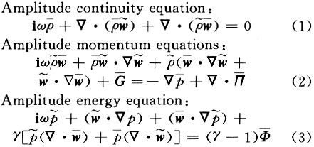
Tsinghua Science and Technology, December 2001, 6(5), pp. 488-491 Oscillating Disturbance Propagation in Passages of Multi-Stage Hydrogen Turbine* LIU Hong Department of Thermal Engineering, Tsinghua University, Beijing 100084, China * Supported by the State Key Developments Plan Project of China (No.G1999022304) Received: 2000-06-29 Code Number: ts01102 Abstract: The propagation of oscillating disturbances with various frequencies in multi-stage turbine passages in a rocket is analyzed using the oscillating fluid mechanics theorem and the parametric polynomial method. The results show that oscillating disturbances can be rapidly dissipated when the disturbance occurs at the inlet except for very high-frequency oscillation such as 50 kHz. Dangerous low-frequency oscillations occur at the outlet. The effects of the flow parameter variations on the oscillating disturbance propagation are also studied. The analysis will facilitate safe operation of the whole rocket system. Key words: flow induced vibration; oscillating fluid mechanics theorem; hydrogen turbine; parametric polynomial method Introduction Flow induced vibrations are a very important problem in rocket systems, because they may cause serious damage to the systems[1 - 3]. The theory of flow induced vibration in rocket flow passages needs to be developed. The complex gas system discussed in this paper includes the combustor, turbine, supplemental combustor, etc. The characteristics of the flow induced vibration in the whole system are analyzed by first studying each element of the system. This paper studies the characteristics of flow induced vibration in a multi-stage hydrogen turbine for oscillating disturbances, for various flow parameter values and oscillating frequencies. These results describe the oscillating pressure distribution not only along the turbine blades, but also along the flow direction. The analysis is based on the oscillating fluid mechanics theorem and the parametric polynomial method[4]. The analytical procedure is as follows: (1) Calculate the 3-D steady flow field in the multi-stage turbine passage; (2) Calculate the 3-D oscillating flow field in the multi-stage turbine passage by solving the 3-D amplitude equations for various oscillating disturbance frequencies, different inlet pressures, inlet temperatures, and rotation speeds. 1 Theory and Analysis The 3-D unsteady N-S equations can be transformed into the amplitude equations in the cylindrical coordinate system using oscillating fluid mechanics theorem[5 - 7].
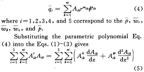
The amplitude equations are solved using the parametric polynomial method. The following is the polynomial form for the flow amplitude parameters:
where j=1, 2, 3, 4, and 5 correspond to the continuity equation, momentum
equation, and engrgy equation, respectively. A'ik
is the parametric polynomial coefficient to be determined. The other parameters
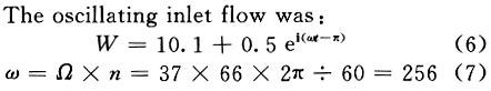
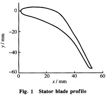
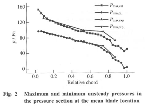
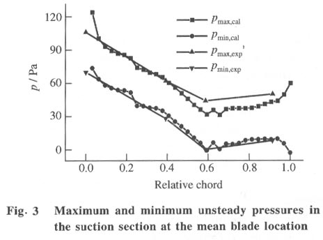
such as 2 Experimental Demonstration of the Numerical Method The results of the analysis and the numerical method are compared to experimental results for a turbine operating in unsteady conditions at Tsinghua University. The stator blade profile is shown in Fig.1 . The machine had 37 stator blades. The stator height was 9 cm. The inlet pressure was 120 Pa (manometer pressure) and the back pressure was 25 Pa (manometer pressure). The inlet total temperature was 280 K. The oscillating inlet flow was:
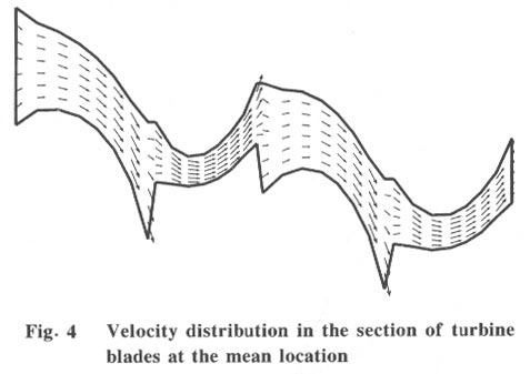
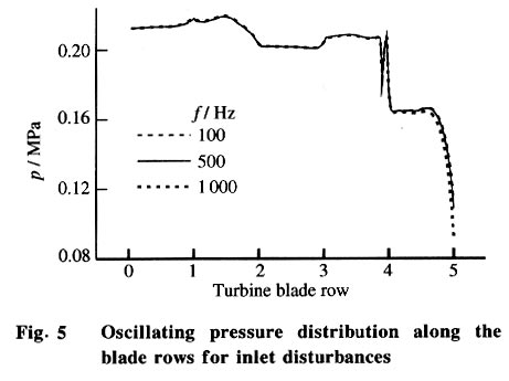
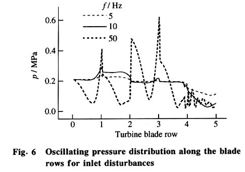
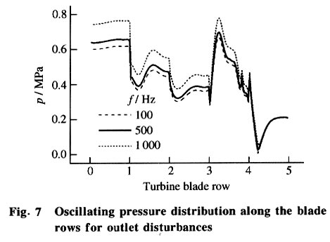
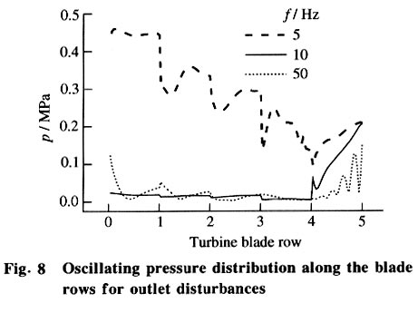
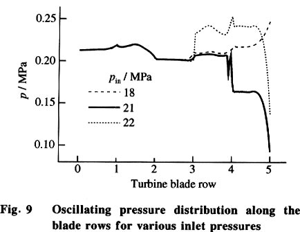
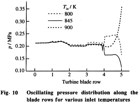
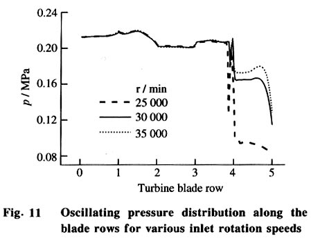
where w represents the basic oscillating frequency, W is the rotational speed and n is the rotor blade number. The inlet velocity, W, was 10.1 m/s with an oscillating amplitude of 0.5 m/s, and -p is the initial phase angle. The unsteady pressure along the blade surface was measured as the maximum and minimum pressures at a period. The calculated results fit well with the experimental data. Figures 2 and 3 show that the numerical method is sufficiently accurate for engineering application. 3 Oscillating Flow Propagation Characteristic in Multi-Stage Turbine Passage for Different Disturbance Frequencies With the oscillating fluid mechanisms theorem, the steady flow equations must be solved before solving the amplitude equations. The 3-D vicous flow for a multi-stage turbine was obtained by solving the 3-D steady N-S equations, Fig. 4. The oscillating flow field was calculated for six frequencies, f1 = 100Hz, f2 = 500Hz, f3 = 1kHz, f4 = 5kHz, f5 = 10kHz, and f6 = 50kHz. The inlet disturbance amplitude was assumed to be 1% of the design pressure. The oscillating pressure distribution on the blade surface along the turbine stage for various frequencies is shown in Figs.5, 6, 7, 8 . The results for disturbances at the inlet are shown in Figs.5 - 6. The results for disturbances at the outlet are shown in Figs.7 - 8. The results show that the oscillating pressure dissipates rapidly along the flow direction at lower frequencies (Fig.6) when the disturbance occurs at the inlet. So if there is no strong oscillation source, the turbine will not be excited by the oscillation. At higher frequencies, the oscillation pressure increases gradually, reaches a maximum then decreases at the end of the first stage. However, the maximum amplitude is less than 0.3 MPa, which is about 1.5% of the inlet pressure. But if the disturbance pressure amplitude is large, such as 3% of the design inlet pressure, the oscillation pressure will exceed the safety limit of 5% of the design pressure. A strong oscillation occurred at a frequency of 50 kHz, but such high frequencies are rare in actual practical projects. For low frequency disturbance at the outlet, the conditions were quite different. The oscillating pressure reached a peak at the end of the first stage and in the middle of the third stage. The peak value was about three times the outlet disturbance pressure, for this multi-stage turbine, downstream oscillations should be avoided. For high frequencies, the oscillation pressure dissipated rapidly. 4 Effect of Flow Parameter Variation on the Oscillating Flow Propagation Characteristic The effect of flow parameter variations on the oscillating flow propagation characteristics was studied for various inlet pressures, temperatures, and rotational speeds. The three inlet pressures Pin were 18, 21, and 22 MPa, the three inlet temperatures Tin were 800, 845, and 900 K, and the three rotational speeds were n1 =25 000 r/min, n2=30 000 r/min, and n3 =35 000 r/min. The calculated results (Figs. 9, 10, 11 ) show the strong effects of the inlet pressure variation on the oscillating flow. The three inlet pressures are greater than, equal to and less than the design pressure. For this turbine, the oscillating pressure amplitude is small for the design conditions (Fig.9). The effect of temperature is shown in Fig.10. The oscillating pressure amplitude first decreases and then increases as the inlet temperature is increased, which suggests an optimal inlet temperature, the design temperature. The oscillating pressure amplitude dissipated quickly with decreasing rotational speed as shown in Fig.11. 5 Conclusions The oscillating fluid mechanics theorem and the parametric polynomial method were used to analyze the oscillating disturbance propagation characteristics in a multi-stage turbine of a rocket. The results demonstrate that the flow induced vibrations in this turbine passage are not serious in most cases, except for lower frequencies with disturbance at the outlet. References
Copyright 2001 - Tsinghua Science and Technology The following images related to this document are available:Photo images[ts01102f6.jpg] [ts01102f2.jpg] [ts01102f10.jpg] [ts01102f8.jpg] [ts01102f4.jpg] [ts01102f7.jpg] [ts01102f3.jpg] [ts01102f5.jpg] [ts01102f9.jpg] [ts01102f1.jpg] [ts01102f11.jpg] |
| |||||||||
