 |
| About Bioline | All Journals | Testimonials | Membership | News |
|
||||||
|
||||||
Tsinghua Science and Technology, December 2001, 6(5), pp. 500-502 Air Breakdown Behavior of Two Series Gaps for Composite Switching Impulse/Alternating Voltage* WANG Liming Department of Electrical Engineering, Tsinghua University, Beijing 100084,
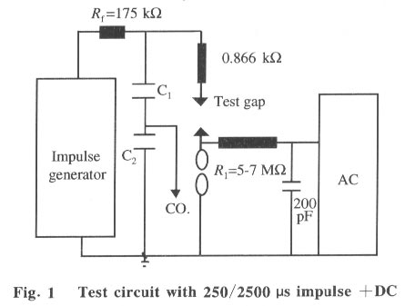
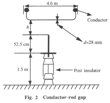
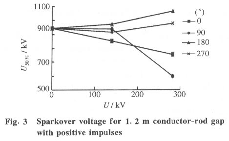
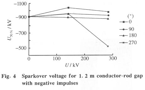
China; *Supported by EPSRC from United Kingdom Received: 2000-09-04; revised: 2000-11-30 Code Number: ts01105 Abstract: More and more high voltage transmission lines make use of rubber housed ZnO arresters in series with another air gap (for example, the insulator gap) as lighting protection elements. Many test results of ZnO arresters protection performance show that this insulation arrangement is suitable for practical lines according to results based on only simple impulse voltage. This paper uses a composite voltage (switching impulse voltage/alternating voltage) to determine the air breakdown behavior of the conductor-rod gap in series with the sphere gap. In the test, the switching impulse voltage is applied to the conductor while the alternating voltage is applied to the rod and one sphere and the other sphere is grounded. The results show that in some cases, the value of the U 50% sparkover voltage for the conductor-rod gap with the composite voltage is nearly only half of that for just the simple impulse voltage. Key words: sparkover; composite voltage; conductor-rod gap Introduction The conductor-rod gap, which represents some of the practical conditions, is known for its high gap factor (about 1.7 ) compared to reference gap (Rod-Plane gap),when a positive impulse is applied to the conductor. This paper analytically investigates the external electrical performance of a line rubber housed ZnO arresters in series with another air gap case, in which the conductor-rod gap is in series with the spheres gap as a sample gap. Much previous work[1-3] has shown that the sparkover voltage characteristics of the conductor-rod gap changes significantly with the pre-stressing alternating voltage and the triggering angle or the direct voltage when the impulse voltage and pre-stressing voltage are applied to the same electrode. In the present work, the impulse voltage is applied to the conductor and the alternating voltage energizes the rod and one sphere. The insulation distance between spheres with diameters of 50 cm, is 10 cm. The maximum peak value of the AC at the spheres gap is 282 kV. 1 Arrangement of the Test Circuit and Test Gap The test circuit is shown[4] in Fig. 1. The impulse voltage across the conductor-rod gap and sphere gap, triggered by a point on the wave, is measured by the capacitor (C1/C2) divider and a 4096 type 200 MHz oscilloscope, since the capacitance of the conductor-rod gap is much smaller than that of the sphere gap. The conductor-rod gap parameters are shown in Fig. 2. The shortest distance between the post insulator and the wall is 4 m. The rod with a 19 mm diameter and a hemispherical tip, is below the middle of the conductor with h as 0.8 m and 1.2 m for the tests. The impulse voltage with the time to peak of 250 ms is superimposed on the alternating voltage at various points (0°, 90), 180), and 270)). The trigger angle at the start of the positive half cycle of the AC is named as 0°. The U50% sparkover voltage is determined using the up-down method based on 45 shots. 2 Test Results 2.1 AC corona When AC voltage at the rod is smaller than 141 kV in the peak, there are no AC streamer corona activities at the rod tip, but for AC voltage greater than 141 kV case, the strength and frequency of the AC streamer corona pulses at the tip of the rod increase with increasing AC voltage . 2.2 Sparkover voltage versus AC for positive impulse voltages The sparkover voltage does not change significantly for all of the trigger angles when the AC voltage is smaller than 141 kV(Fig. 3), but the sparkover voltage changes dramatically when the AC voltage is bigger than 141 kV. The sparkover voltage increases when triggered at 180° and 270°, decreases at 0° and decreases significantly when triggered at 90°. An especially large decrease (about 60% reduction compared to that for AC voltage at 0 kV) occurred for 282 kV at 90°. The spreads of the sparkover voltages were within 3% and had no significant change with the change of the alternating voltage. 2.3 Sparkover voltage versus AC for negative impulse voltage For the 0.8 m gap, the sparkover voltage versus AC voltage had the same trend as for the positive impulse when the AC voltage was less than 141 kV. When the AC voltage was larger than 141 kV, the sparkover voltage tended to increase at a trigger angle of 180°, to decrease at the trigger angle of 0° and 90° and to decrease significantly at the trigger angle of 270°. For the 1.2 m gap (Fig. 4), increasing the AC voltage from 0 to 282 kV, tended to cause a small increase in sparkover voltage at trigger angles of 0° and 90°, a small decrease at a trigger angle of 180°, but a large decrease at a trigger angle of 270°. The spreads of the sparkover voltage were within 2.5% and also had no significant change with changes of the alternating voltage. 3 Time to Breakdown The time to breakdown at the smallest sparkover voltage point (90), 282 kV) for positive impulses is larger than that for 0 kV AC, but for other cases, the time to breakdown did not change much as the AC voltage changed. For negative impulses, the time to breakdown at the smallest sparkover voltage point (270), 282 kV) was much less than that for 0 kV AC, but for other cases, the time to breakdown also did not change much with the AC voltage. The spreads of the time to fHJ*6﹏ breakdown were within 40% and tended to gradually decrease with increasing AC voltage at all the trigger angles. 4 Discussion Allen and Wang[1,5,6] showed that for a conductor-rod gap with the AC and impulse voltages applied to the conductor (rod grounded), the sparkover voltage increased greatly (about 70% - 80%) with increasing AC voltage at trigger angles of 135° and 180°. The results can be clearly explained by analyzing the effect of the AC streamer corona along the conductor on the impulse corona. In the present case, no AC streamer corona was detected by the photo-multiplier except for the glow corona and the impulse corona along the conductor which were not significantly different with and without the AC corona. Therefore, this implies that the AC streamer corona on the rod does not significantly affect the sparkover voltage compared with that along the conductor. For the positive impulse with the AC voltage of 282 kV at 90°, many streamer corona pulses occurred along the conductor, with no corona on the rod tip. Therefore, the discharge started from the sphere gap about 2 - 5 ms earlier than from the conductor-rod gap. This did not occur in the other tests. This phenomenon may be the main reason causing the weak electrical performance of the conductor-rod gap. 5 Conclusions (1) The behavior of the sparkover voltage is a very complex phenomenon because of the effect of the AC voltage. It not only depends on the AC voltage and triggering angles, but also on how the voltages are. (2) The present paper shows that the smallest sparkover voltage occurs at a trigger angle of 90°( 282 kV ) for positive impulses and at 270°( 282 kV ) for negative impulses. The value of the smallest sparkover voltage is about 60% of that without the pre-stressing AC voltage. References
GUAN Zhicheng, Professor of Department of Electrical Engineering, Vice President of Tsinghua University Council, Chairman of Academic Committee of Electrical Engineering Department, Vice Chairman of Editorial Committee of ~iTsinghua Science and Technology. He was born on November 10, 1944, in Jilin Province of China. He graduated from Tsinghua University in 1970. He got Master degree and Ph.D both in High Voltage Engineering from Tsinghua University in 1981 and 1984 respectively. From 1987 to 1989 he was a visiting scholar in UMIST of UK. His research areas include: High Voltage Insulation, Electrical Discharge and Plasma, Electrical Environment Technology, High Voltage Measurement,etc. He won a Third Class Award of Natural Science Study granted by the State for "Study on the Discharge along the Polluted Surface of Insulators" and a Second Class Award of Science and Technology Advancement granted by the State for "R & D of UHV Composite Insulators". He also won 9 Awards of Science and Technology Advancement granted by the State Education Commission (Ministry of Education, China) or by the Ministry of Power Industry. In recognition of his outstanding research achievements he is a Winner of the title "Ph.D. Degree Bearer with Outstanding ontributions" and the title "Young Expert with Outstanding Contributions". He has published more than 160 academic papers. He is also the Vice President of Chinese Society for Electrical Engineering and the Vice President of Chinese Electrotechnical Society. Copyright 2001 - Tsinghua Science and Technology The following images related to this document are available:Photo images[ts01105f4.jpg] [ts01105f3.jpg] [ts01105f2.jpg] [ts01105f1.jpg] |
| |||||||||